You must Sign-in or Register to post messages in the Hobby Squawk community
Registration is FREE and only takes a few moments

Register now

Announcement

Collapse
No announcement yet.

Roban 700 AS350 Air Zermatt Superscale Build

Collapse
X
Collapse
First Prev Next Last
 
  • Filter
  • Time
  • Show
Clear All
new posts

  • Roban 700 AS350 Air Zermatt Superscale Build

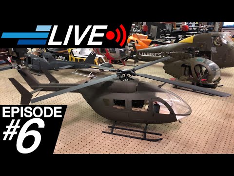
    Introducing the Roban 700 size AS350 Air Zermatt Superscale helicopter. Air Zermatt is an Alpine rescue and commercial aviation company that specializes in helicopters. Roban has provided a highly detailed scale rendition of their beautiful red and white star AS350 Écureuil in the 700 size class. The size, detail and finish of this helicopter is impressive to say the least. The kit comes complete with mechanics and blades and features a basic interior with seats, instrument panel, functional doors and a sliding rear door on the left side. The unboxing was featured in the latest Motion RC Live episode #6 shot largely at TiredIron Aviation so check that out if you want to see the packaging and what comes in the box.


    I will be getting lots of pics and documenting the build here. It really is a gorgeous heli. The front is held on with magnets and takes a pretty good tug to get it loose but ships with two M3 screws on each side that keep it secure for transport. Here are the locations but with the screws removed.

    Click image for larger version  Name:	IMG_20200216_005800-1944x1458.jpg Views:	0 Size:	97.7 KB ID:	236753

    Click image for larger version  Name:	IMG_20200216_005808-1944x1458.jpg Views:	0 Size:	90.6 KB ID:	236754

    The manual appears to be fairly straightforward and notes that installation of the motor requires the removal of one of the side frames so they have purposefully left the screws on one side loose for that reason. The mechanics, while they share many components with the 700 Apache do have different side frames.

    Click image for larger version  Name:	IMG_20200216_005837-1944x1458.jpg Views:	0 Size:	170.3 KB ID:	236757

    A light kit contains 4 LED's, a control board and 4 lenses (1 - green, 1 - clear and 2 - red). The three blade rotor head has metal blade grips while the two blade tail rotor utilizes plastic grips. Here is a shot of the entire kit.

    Click image for larger version  Name:	IMG_20200215_195646-1944x1458.jpg Views:	0 Size:	208.1 KB ID:	236756

  • #2
    I'm surprised how complete the kit is, down to the dash and seats...choose your electronics and go.
    TiredIron Aviation
    Tired Iron Military Vehicles

    Comment


    • #3
      Yup. There are a few water-slide decals to put on it but they should look great over the finish. Something else to note is the scale is about 1:6.7'ish or call it 1/7th so about a 10" pilot figure.

      Comment


      • #4
        A 1/7 scale figure should fit nicely --ever so slightly undersized to ensure his feet clear the pedals.

        I appreciate the engineering that goes into the mechanics and the meticulous craftsmanship on these higher-end Robans. I've seen the molds up close, from the gelcoat/fiberglass molds for large pieces down to the small silicone molds for the various interior detail parts. Those silicone molds have a limited lifespan, so the factory is continually striking new molds from the masters to keep up with production.
        Live Q&A every Tuesday and Friday at 9pm EST on my Twitch Livestream

        Live chat with me and other RC Nuts on my Discord

        Camp my Instagram @Alpha.Makes

        Comment


        • #5
          Progress on the AS-350. The instruction manual starts with attaching the rotor head to the main shaft and then assembling the tail boom but I wanted to first get some feet under this bird so I started with the landing gear. The gear struts on the AS-350 unlike many are two parts as they plug into the sides of the fuselage. They are made from aluminum tube and painted white. To secure the M3 screws in the rear locations you will need a driver with a long extension. I recommend dry fitting the screws into the blind nuts to make sure the threads are clear. Here is where I ran into my first hurdle. The mounting holes on the rear struts caused an alignment issue that created a cross threading situation. I enlarged the holes slightly in the struts and no more problem. Once the rear cross braces were secured I mounted the front cross tubes and immediately noticed two things. First, the struts were much wider at the front than the rear which made it look goofy.

          Click image for larger version  Name:	IMG_20200220_201342-1944x1458.jpg Views:	0 Size:	195.9 KB ID:	237906
          Second, the front of the one skid was much higher than the other which made it rock when it was sitting.

          Click image for larger version  Name:	IMG_20200220_201329-1944x1458.jpg Views:	0 Size:	184.8 KB ID:	237907
          Both issues would have to be corrected. The wider stance on the front was easy as I just re-drilled the mounting holes in the front cross tubes.

          Click image for larger version  Name:	IMG_20200221_224009-1944x1458.jpg Views:	0 Size:	121.6 KB ID:	237908
          The warped strut was a harder thing to overcome. I tried to straighten it while installed in the fuse but could not exert enough force on it without being concerned of breaking something. I removed the struts from the fuse and inserted two drill bits into the cross tubes to check square and on the bench they looked good. I re-installed them and they were warped again. Perhaps mine had an issue with the wood framework mounted in the fiberglass fuse? I dunno but what I did was to take them out again, install the drill bits and this time I twisted them to build in some opposite warp while sitting on the bench which was much easier to do. Now when I installed them they were even....

          Click image for larger version  Name:	MVIMG_20200224_022225-1944x1458.jpg Views:	0 Size:	186.8 KB ID:	237910

          and looked much better!

          Click image for larger version  Name:	IMG_20200221_212958-1944x1458.jpg Views:	0 Size:	178.0 KB ID:	237909

          Comment


          • #6
            Looking great!!
            Roy Mayoral

            Comment


            • #7
              I'm building the same heli, although it is a different color scheme. Have you gotten to the point of balancing the whole heli? If so, did you have to add weight to the front end and about how much?

              Thanks.

              Comment


              • #8
                Originally posted by K_Young52 View Post
                I'm building the same heli, although it is a different color scheme. Have you gotten to the point of balancing the whole heli? If so, did you have to add weight to the front end and about how much?

                Thanks.
                I haven't gotten to the point of balancing it yet. Still don't have the running gear for it but I am thinking it will require some up front.

                Comment


                • #9
                  I've built 2 of these AS350's and they are very tail heavy especially if you're going to put the batteries in the slots under the mechanics. I moved mine under the cockpit floor and still had to add lead weight to get it balanced. Here's how I have configured mine.

                  Click image for larger version  Name:	as350_battery compartment.jpg Views:	4 Size:	94.1 KB ID:	248847

                  Comment


                  • #10
                    Good to know It1pwr. Thank you for the input.

                    Comment


                    • #11
                      I thought I would have to add a lot of weight. I had not thought about placing the batteries under the flight deck. I'll check to see if my batteries will fit. I have posted two pictures. I added plastic box to hold the weights. I also added a post (3mm machine screw) to the nose to hold the canopy in place. I don't like having to use the two machine screws to secure the canopy. I want to be able to get to the batteries quicker. I don't trust the magnets already installed in the canopy to hold it on without those machine screws so I added the post and two more magnets. The magnets sit under the two black X's and the washers you can see in the picture of the underside of the canopy.

                      Click image for larger version

Name:	IMG_2128.JPG
Views:	833
Size:	63.1 KB
ID:	248879Click image for larger version

Name:	IMG_2129.JPG
Views:	831
Size:	74.6 KB
ID:	248878Click image for larger version

Name:	IMG_2128.JPG
Views:	785
Size:	63.1 KB
ID:	248880
                      Attached Files

                      Comment


                      • #12
                        Good idea adding the extra post and magnets. My cabin has a fair amount of weight to it and luckily the magnets that came with the fuse hold really well.

                        Click image for larger version

Name:	as350_battery compartment-2.jpg
Views:	713
Size:	142.6 KB
ID:	248894

                        Comment


                        • #13
                          All,

                          I would like to know how the foam dampeners are installed. A picture would be great. It seems to me they need to be glued to the doghouse and not the main frame. If they are glued to the main frame it doesn't appear you can slide the mechanics into the fuselage.

                          Thanks.

                          Comment

                          Working...
                          X