

P-38 - The Ultimate EPO Lightning

Official Freewing MiG-29 Fulcrum Twin 80mm Thread

Collapse
X
Collapse
First Prev Next Last
 
  • Time
  • Show
Clear All
new posts
  • KevinMar
    Member

    • Oct 2020
    • 67
    • Send PM

    #5341
    I wish they'd let us know ahead of time like the previous price increase

    Comment

    • Skosh25
      Member

      • Mar 2019
      • 177
      • Denver
      • Send PM

      #5342
      Originally posted by Hugh Wiedman
      Very nice Skosh25 , always liked your scheme! Great flight and landing. Still looks a little cold out there!
      Thanks I hadn’t flown it in a couple weeks so landing was a bit harder than I would have liked. Subsequent landings were better.

      it was actually in the mid 60s that day!

      Comment

      • pullupnow
        Pilot

        • Feb 2018
        • 70
        • Long Island NY
        • Send PM

        #5343
        Originally posted by Skosh25
        Had some great flights with mine this past weekend. Probably north of 150 total now!
        Beautiful flight! smooth... Looks like you're getting the Mig toe out on the main gear due to the high cycles. Glider Guy's simple fix by bending the rotation pins slightly to correct the toe out works perfectly. It will save you a bunch in tire wear! ask me how I know. Keep up the awesome flying!

        Comment

        • GliderGuy
          Senior Member

          • Oct 2018
          • 1408
          • Send PM

          #5344
          Originally posted by pullupnow

          Beautiful flight! smooth... Looks like you're getting the Mig toe out on the main gear due to the high cycles. Glider Guy's simple fix by bending the rotation pins slightly to correct the toe out works perfectly. It will save you a bunch in tire wear! ask me how I know. Keep up the awesome flying!
          Yes….bending the main axle pins slightly works great!

          I also found that toe out can be a symptom of the main’s plastic mounting box becoming loose and/or the foam supporting the box becoming mushy.

          A bit of carbon added in strategic places (remove the wing) around the plastic mounts works wonders.

          Now…when the plastic mount(s) crack, you’ve got your work cut out for you to replace them. Reference my prior posts covering this headache.

          They are not designed to be replaceable, but you can do it. You can’t get to the screws that secure the plastic mounts.

          -GG

          Comment

          • Skosh25
            Member

            • Mar 2019
            • 177
            • Denver
            • Send PM

            #5345
            Originally posted by GliderGuy

            Yes….bending the main axle pins slightly works great!

            I also found that toe out can be a symptom of the main’s plastic mounting box becoming loose and/or the foam supporting the box becoming mushy.

            A bit of carbon added in strategic places (remove the wing) around the plastic mounts works wonders.

            Now…when the plastic mount(s) crack, you’ve got your work cut out for you to replace them. Reference my prior posts covering this headache.

            They are not designed to be replaceable, but you can do it. You can’t get to the screws that secure the plastic mounts.

            -GG
            Thanks- I hadn’t even noticed the toe until I watched the video. I’ll give that a shot.

            Comment

            • GliderGuy
              Senior Member

              • Oct 2018
              • 1408
              • Send PM

              #5346
              Skosh25….here is the post

              Freewing MiG-29 Fulcrum Twin 80mm EDF Jet​ Freewing first established the Twin 80mm class of EDF jets with its popular F-14 Tomcat and then the A-10 Warthog, and now we are proud to announce the Freewing MiG-29 Fulcrum! Represented in 1/9 scale, this large aircraft is 1878mm (74”) long with a 1257mm (50”) wingspan,


              -GG

              Comment

              • radfordc

                • Jul 2017
                • 375
                • Lansing, KS
                • Send PM

                #5347
                Originally posted by GliderGuy

                I also found that toe out can be a symptom of the main’s plastic mounting box becoming loose and/or the foam supporting the box becoming mushy.

                A bit of carbon added in strategic places (remove the wing) around the plastic mounts works wonders.

                -GG
                Are there pictures of what you did to reinforce the gear mounts? I'm starting putting a Mig together. Better to do the fix now than after the gear are loose.

                Comment

                • GliderGuy
                  Senior Member

                  • Oct 2018
                  • 1408
                  • Send PM

                  #5348
                  Originally posted by radfordc

                  Are there pictures of what you did to reinforce the gear mounts? I'm starting putting a Mig together. Better to do the fix now than after the gear are loose.
                  For starters....here's the start of the posts about the plastic gear mount replacement process for your files and future reference. What a pain! The photo shows the mount area after you get the plastic mount out. WHAT A PAIN THAT WAS! it doesn't leave the area looking very pretty, either. But, this can be filled/repainted after the grunt work is finished and the new plastic mount installed. MRC support said, "The plastic mounts were not meant to be replaced."

                  https://www.hobbysquawk.com/forum/rc...385#post332385

                  PLEASE NOTE: YOU DO NOT NEED TO REMOVE THE PLASTIC MOUNT TO REINFORCE THE AREA!

                  I just happened to take the photo when I was doing the plastic mount replacement.

                  Now to answer your question: Primarily, the thin foam shelf on the outside (the side towards the wing tip) of the hole that the plastic gear mount sets in gets soft and mushy after a time.

                  Note: For the rest of my post, consider the MiG is upside down as in the photo. I wasn't concerned about how "pretty' this all looked because it is covered by the wing, once you put the wing on.

                  With the wing off, you will note on the fuselage there is an area of foam below (towards the floor) the thin outside edge of the plastic gear mount. If you carefully cut (watch for wires, spars, etc.) a notch into this foam and insert some carbon "under" the area of the outside thin shelf, it will strengthen this area significantly. It holds up REALLY well.

                  Glue in the carbon with your adhesive of choice, Foam Tac, epoxy, hot glue, etc. Whatever you think is best. I used JB Kwik Weld epoxy which has a 3000 psi strength. Slow cure epoxy will be even stronger.

                  -GG

                  Aside: Since one must cut the mount's 3 screws off with a Dremel tool to get the plastic mount out piecemeal (you gotta cut it out in small pieces), when I reset the new mount in the hole, I used epoxy to secure the plastic box and basically replace the function of the screws. Hundreds of landings later....the mount remains solidly attached.

                  PS: The reason the vertical wall is white is I glued some carbon sheet to this wall and then made an angle brace from the carbon sheet to the plastic mount. It turns out that this vertical wall is VERY thin and will tear easily when the carbon sheet is removed or the carbon sheet shears from a hard landing. In hind site, I don't think I would try attaching anything to this thin wall of foam that might put stress on the thin wall. It is not made to withstand any stress. It's only purpose is to form the wall of the air duct to the EDF fan. Lesson learned.....

                  Click image for larger version  Name:	MiG_Reinforcement.jpg Views:	0 Size:	50.4 KB ID:	341268

                  Comment

                  • radfordc

                    • Jul 2017
                    • 375
                    • Lansing, KS
                    • Send PM

                    #5349
                    Like so.
                    Click image for larger version

Name:	IMG_20220402_104134927.jpg
Views:	807
Size:	46.3 KB
ID:	341300

                    Comment

                    • GliderGuy
                      Senior Member

                      • Oct 2018
                      • 1408
                      • Send PM

                      #5350
                      Originally posted by radfordc
                      Like so.
                      Click image for larger version

Name:	IMG_20220402_104134927.jpg
Views:	807
Size:	46.3 KB
ID:	341300
                      perfect!

                      Comment

                      • radfordc

                        • Jul 2017
                        • 375
                        • Lansing, KS
                        • Send PM

                        #5351
                        I can see how it helps tie the gear into the two plastic wing retainer mounts. Good idea.

                        Comment

                        • Falcon195
                          Member
                          • Jan 2022
                          • 9
                          • Send PM

                          #5352
                          Here is a question. I see this Mig29 reguires two 6s batteries. Are these batteries connected parallel or series? I am thing they are connected in parallel and is set up for 22 2 volts. Am I correct?

                          Comment

                          • xviper
                            Hobby Squawk Regular

                            • Jan 2014
                            • 8755
                            • Calgary, Canada
                            • Send PM

                            #5353
                            Hint: This is a 6s power system. Hooked up in series, it would be a 12s system.

                            Comment

                            • GliderGuy
                              Senior Member

                              • Oct 2018
                              • 1408
                              • Send PM

                              #5354
                              Originally posted by Falcon195
                              Here is a question. I see this Mig29 reguires two 6s batteries. Are these batteries connected parallel or series? I am thing they are connected in parallel and is set up for 22 2 volts. Am I correct?
                              Actually….Neither.

                              The MiG-29 has two “systems” totally separate. One battery drives one ESC/motor and the BEC. While the other battery drives the second ESC/motor only.

                              The + of one battery never sees the + of the other battery. Ditto for the - battery terminals.

                              I have my P-38 systems wired in parallel. When one battery Is connected ALL systems become alive….both ESCs, and the BEC. When I connect the second battery….nothing more becomes live. The + of both batteries now “see” each other. Ditto for the - terminals. I did this because the P-38 instantly and violently rolls when one motor fails. Now wired in parallel, EITHER battery can keep both props turning.

                              Now you COULD wire the MiG-29 like I wired my P-38. But why? The MiG-29 won’t violently roll if just one motor stops. A parallel wired MiG-29 would, however, keep ALL systems working if the critical (BEC) battery started to sag.

                              So what if the MiG-29 battery powering the BEC+motor sags? If the voltage gets low enough, you may have your hands full. In this respect, physically wiring the MiG-29 in parallel does add a measure of security. The decision is up to you!

                              One IMPORTANT note….flight times don’t change just because you decide to make the batteries parallel in the case of the MiG-29 or P-38. The total system before wiring in parallel is: 2 motors, 2 ESCs, BEC, and the loads on the BEC AND 2 batteries. After you do the wiring, the total system DOES NOT change.

                              Now take an AL37 (one battery driving everything) and wire in a SECOND battery in parallel, you will dramatically increase your flight time. But notice, you CHANGED the system. You went from one battery to two.

                              And some use a separate battery just for the BEC+ its loads. It’s not connected to anything but the BEC. Now you don’t depend on a heavily loaded flight battery to power the BEC and its loads = added security. Note: Read your radio manuals...some provide additional guidance for implementing this set-up specifically for their radio.

                              -GG

                              Comment

                              • Airguardian
                                Post Stall Svengali

                                • Aug 2020
                                • 1664
                                • Catalonia
                                • Send PM

                                #5355
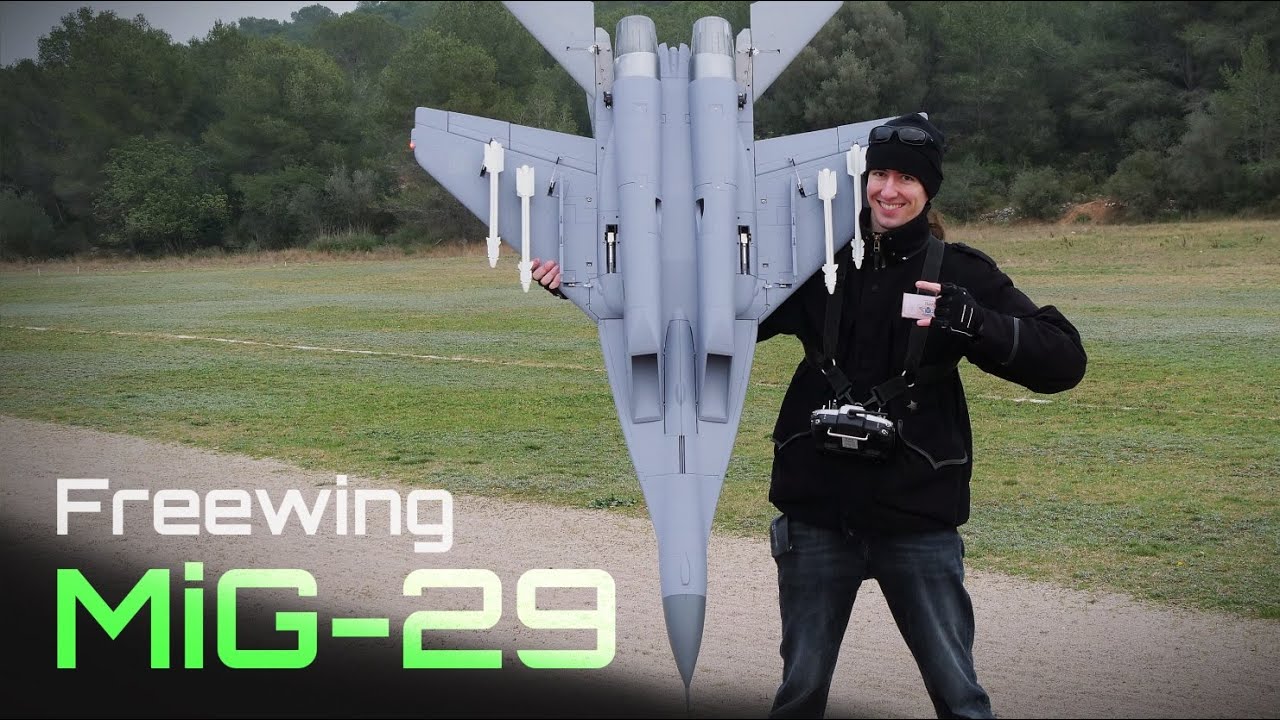
                                Time for some more Fulcrum shenanigans!
                                Comment

                                • jasmith41
                                  EDF-obsessed
                                  • Sep 2021
                                  • 316
                                  • AZ and NE Ohio
                                  • Send PM

                                  #5356
                                  Originally posted by Airguardian
                                  Time for some more Fulcrum shenanigans!

                                  Great vid - mine is still in box in office. I may actually buy and fly their SU35 before the 29...

                                  What's your general rule of thumb on CG? Do you always go by the book, back a bit, forward a bit, depends on the jet, etc....?

                                  Comment

                                  • Airguardian
                                    Post Stall Svengali

                                    • Aug 2020
                                    • 1664
                                    • Catalonia
                                    • Send PM

                                    #5357
                                    There is no golden rule of thumb but most manufacturers tend to recommend overly nose heavy setups.
                                    The way to go is through in-flight testing to determine whether a CG is too far forward or aft and converge on a more neutral spot (accounting for pilot preferences, obviously).

                                    Thankfully for you, this jet has been tested thoroughly by many people in this thread and others, and mostly everyone will agree and recommend to set the CG 15mm behind the factory-molded CG marks on the wings. Not any forward, not any further aft.
                                    Fwd of that is too nose heavy, and aft of that the plane's capability to recover from a high alpha lock without help of thrust vectoring nozzles diminishes substantially.

                                    If you are using vectored nozzles, then you should be fine to experiment beyond 20mm aft of the CG molded marks without much trouble (always doing so with common sense, in incremental steps and following a sound method, of course).

                                    Comment

                                    • jasmith41
                                      EDF-obsessed
                                      • Sep 2021
                                      • 316
                                      • AZ and NE Ohio
                                      • Send PM

                                      #5358
                                      Originally posted by Airguardian
                                      There is no golden rule of thumb but most manufacturers tend to recommend overly nose heavy setups.
                                      The way to go is through in-flight testing to determine whether a CG is too far forward or aft and converge on a more neutral spot (accounting for pilot preferences, obviously).

                                      Thankfully for you, this jet has been tested thoroughly by many people in this thread and others, and mostly everyone will agree and recommend to set the CG 15mm behind the factory-molded CG marks on the wings. Not any forward, not any further aft.
                                      Fwd of that is too nose heavy, and aft of that the plane's capability to recover from a high alpha lock without help of thrust vectoring nozzles diminishes substantially.

                                      If you are using vectored nozzles, then you should be fine to experiment beyond 20mm aft of the CG molded marks without much trouble (always doing so with common sense, in incremental steps and following a sound method, of course).
                                      Thank you...! Seems most lean back on CG from book rates...

                                      Comment

                                      • Evan D
                                        I'll fly anything

                                        • Jan 2016
                                        • 5387
                                        • Charlotte
                                        • Send PM

                                        #5359
                                        Mine is about 5mm behind the marks but sometimes I do 10mm. I do have the full span reflex in mine and TVs. Before the reflex and TVs I was a little further aft, 10-15mm behind the mark.

                                        Comment

                                        • jasmith41
                                          EDF-obsessed
                                          • Sep 2021
                                          • 316
                                          • AZ and NE Ohio
                                          • Send PM

                                          #5360
                                          Originally posted by Evan D
                                          Mine is about 5mm behind the marks but sometimes I do 10mm. I do have the full span reflex in mine and TVs. Before the reflex and TVs I was a little further aft, 10-15mm behind the mark.
                                          Thanks man...

                                          Comment

                                          Working...