You must Sign-in or Register to post messages in the Hobby Squawk community
Registration is FREE and only takes a few moments

Register now

Announcement

Collapse
No announcement yet.

Official Black Horse 2350mm Gilmore Red Lion

Collapse
X
Collapse
First Prev Next Last
 
  • Filter
  • Time
  • Show
Clear All
new posts

  • Official Black Horse 2350mm Gilmore Red Lion

    Gilmore 2350mm (92.5") Wingspan from Black Horse - Balsa Wood ARF - BHM1003-001


    Roscoe Turner was the preeminent aerial showman of the 1930s, and perhaps of all time. From 1929 to 1930, Turner set numerous cross-country speed records and won many air races. To raise publicity while he was flying for the Gilmore Oil Company in the early 1930s, Turner adopted a lion cub and flew with him until he became too large. A lion’s head was the logo for the Gilmore Oil Company, and Turner named the cub Gilmore. Turner retired from air racing in 1939, but continued to be involved in aviation until his death, which, unlike for so many early aviators, was from natural causes.

    The model is scaled to approximately 1:5 and attention was paid to a true to original appearance and best flight characteristics. The model can be operated using an electric power system or with an internal combustion engine about 60cc displacement.
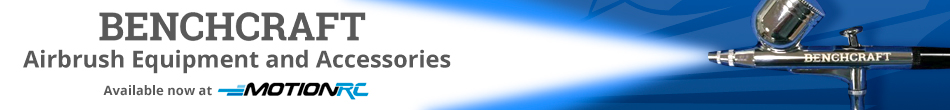
    Classic Racing Livery


    The racing scheme is a tip of the cap to the golden era when barnstorming was a house-hold term.
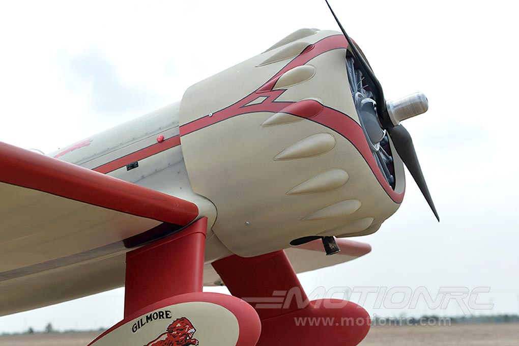
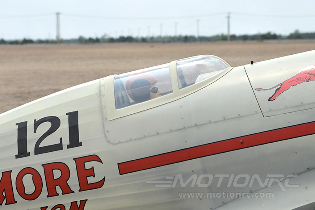
    Factory Weathered Printing


    The printing on this model has a realistic weathering complete with rivet and panel line detail that elevates the model to a whole new level of scale appeal. The "faded" weathering is subtle and accentuates the fully sheeted areas and the ribbed areas of the fuselage nicely, flowing with the contours of each shape. Because this weathering is silk-screen printed onto every model, it always matches, in case you needed to buy a spare wing after a crash.
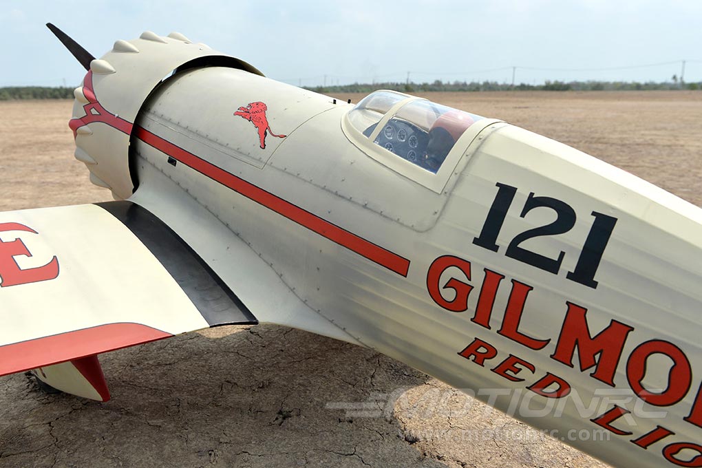
    Fiberglass Molded Cowl


    Exceptional quality fiberglass molded cowl really adds to the realism and scale appeal. Very subtle shading and meticulous pin-striping really accentuates the classic lines of this aircraft.
    Gas or Electric Power for this ~1/3 scale Racer!


    You can choose between gas or electric to power your model depending on your preference. The huge frontal area makes installations of either powerplants very easy.
    Large Electronics Hatch


    There is ample room for your various electronics, batteries, gyros or anything you desire to complete your electrical system. The Gilmore Red Lion has a cavernous fuselage, so space is not a concern!
    Scale Racing Canopy


    The canopy has the scale outline and look of the original from the 1930's. Even the pilot looks like he's reaching for the finish line!
    FEATURES:
    • High level of prefabrication right out of the box
    • ~1/3.4 scale
    • Lightweight, strong, laser cut balsa and plywood construction
    • Classic racing scheme with subtle pre-printed shading
    • Panel lines and details printed directly onto the pre-applied, high quality covering
    • Aerofoiled tail surfaces
    • Recessed hinges on all control surfaces
    • Pre-drilled hinge mounting holes
    • Heavy-duty pin hinges on all control surfaces
    • Large easy access fuel tank/battery/servo access hatches with sprung loaded latches
    • Painted and detailed cockpit, pilot and interior included
    • Fiberglass control horns with ball link connector
    • comprehensive control and fitting accessories included
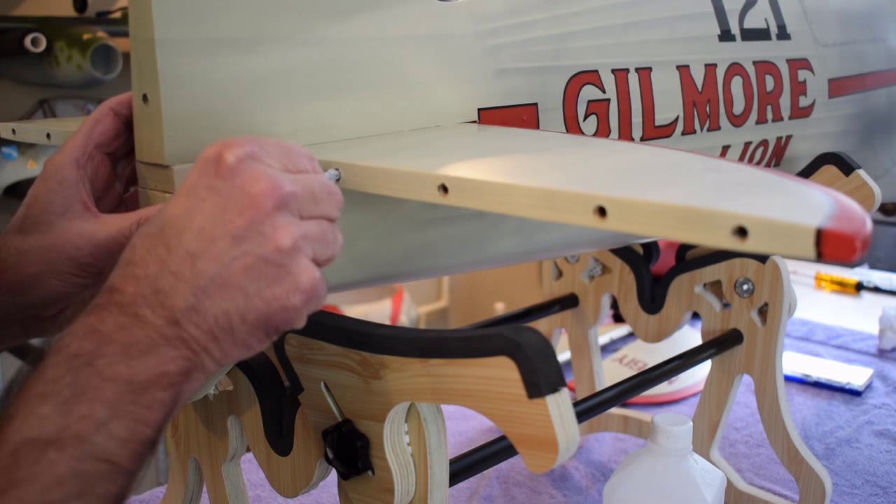
    • Two-piece, plug-in wings simplify transportation and assembly
    • Fiberglass cowl and glass reinforced landing gear covers/pants
    • Mounts for both electric and gas power options included
    Live Q&A every Tuesday and Friday at 9pm EST on my Twitch Livestream

    Live chat with me and other RC Nuts on my Discord

    Camp my Instagram @Alpha.Makes

  • #2
    This is a build and review for the 92.5” wingspan, 60cc Gilmore Red Lion by Back Horse Model and distributed by Motion RC. We’ll cover the unboxing, build, and initial flight.

    Unboxing:
    Packaging: The plane comes double boxed. All components boxed separately inside. All parts are wrapped in plastic and or bubble wrap.

    Condition: Some lifting of covering at overlap seam on fuselage. No major wrinkles in covering. No damage from packing or shipping.


    Initial Impression: The first thing you notice is the size. The front of the fuselage is about 14” in diameter and the cowl is about 15” at the blisters.
    Next is the covering. It has a matt finish and has printed details that give the impression of rivets and panel lines. The plane is weathered to replicate a period racer that has run several full throttle heats around the pylons. The exhaust and oil accumulation is believable. A closer look shows minute details that resemble what you would see if the plane was covered in fabric. I understand that Black Horse uses a multi-layered printing process to achieve this.
    It has a nicely done 3d instrument panel. All control surfaces are pre-drilled for “hinge point” type hinges. Hardware appears to be good quality and is individually bagged by construction step.

    The major airframe components seem to be well constructed using quality adhesives and materials. I saw no areas that needed re-gluing or modifications. The attention to detail in the construction practices is worth noting. The balsa sheeting in the nose and wing fillet areas, with its many compound curves is quite well done. The formers have been scalloped where the stringers pass through. This is a technique used by skilled builders and rarely seen on ARFs. Those that have done finishing know that “prep work is everything”. The prep work on this model is done better than many I’ve seen.

    What’s in the box: All major airframe components, landing gear(main and tail), wheels, cowl, dummy motor, pilot, pushrods, hinges, mount templates for DLE 55cc and 61cc gas motors, gas engine mount spacers and mount bolts. Fuel tank. Electric motor adapter with spacers and bolts, aluminum wing tube, a CG checking toolkit, additional decals, 46 page instruction manual, and a spare piece of covering for repairs if needed.


    Click image for larger version

Name:	
Views:	0
Size:	89.5 KB
ID:	239991Click image for larger version

Name:	
Views:	0
Size:	121.3 KB
ID:	239992Click image for larger version

Name:	
Views:	0
Size:	77.6 KB
ID:	239993Click image for larger version

Name:	
Views:	0
Size:	102.3 KB
ID:	239994Click image for larger version

Name:	
Views:	0
Size:	94.4 KB
ID:	239995Click image for larger version

Name:	
Views:	0
Size:	94.8 KB
ID:	239996

    Comment


    • #3
      Looks good, Twowingtj, keep us updated on your progress! The Gilmore Red Lion Racer 121 is such a slick looking aircraft to me. I believe the original aircraft can be seen at Patterson AFB according to Google:

      Click image for larger version

Name:	b7c70d4f-3a1e-4102-a889-ef6c1e3c3a61_l.jpg
Views:	4413
Size:	61.0 KB
ID:	240023


      Live Q&A every Tuesday and Friday at 9pm EST on my Twitch Livestream

      Live chat with me and other RC Nuts on my Discord

      Camp my Instagram @Alpha.Makes

      Comment


      • #4
        Originally posted by Alpha View Post
        Looks good, Twowingtj, keep us updated on your progress! The Gilmore Red Lion Racer 121 is such a slick looking aircraft to me. I believe the original aircraft can be seen at Patterson AFB according to Google:

        Click image for larger version  Name:	b7c70d4f-3a1e-4102-a889-ef6c1e3c3a61_l.jpg Views:	0 Size:	61.0 KB ID:	240023


        This is a really nice bird!

        As for the scale, the product page says 1:5. My calculations came to 1:3.4 or just shy of 30%.

        Comment


        • #5
          I just ordered mine today. I had a previous Blackhorse version of this I flew at 2016 scale masters. I think it was a slightly smaller scale? It flew great! I'm very excited to get this one! My first was gas but I'm considering electric on this one.
          There are hundreds of RC aviation videos viewable here; WBRC

          Comment


          • #6
            Originally posted by WrightBrosRC View Post
            I just ordered mine today. I had a previous Blackhorse version of this I flew at 2016 scale masters. I think it was a slightly smaller scale? It flew great! I'm very excited to get this one! My first was gas but I'm considering electric on this one.
            Congrats on your win and thanks for your purchase! This bird is larger than the previous version you flew. From your trophy photo, it appears yours was Black Horse's .46 size bird (1470mm wingspan), while this one on this thread that you just ordered is the 60cc size bird (2350mm wingspan).
            Live Q&A every Tuesday and Friday at 9pm EST on my Twitch Livestream

            Live chat with me and other RC Nuts on my Discord

            Camp my Instagram @Alpha.Makes

            Comment


            • #7
              Originally posted by Alpha View Post

              Congrats on your win and thanks for your purchase! This bird is larger than the previous version you flew. From your trophy photo, it appears yours was Black Horse's .46 size bird (1470mm wingspan), while this one on this thread that you just ordered is the 60cc size bird (2350mm wingspan).
              Thx! You know the saying... bigger flies better!
              There are hundreds of RC aviation videos viewable here; WBRC

              Comment


              • #8
                WrightBrosRC mine is electric powered as well. The Black Horse Gilmore is designed well for both electric and gas power. I'll be posting more details on the build shortly.

                Comment


                • #9
                  Originally posted by Twowingtj View Post
                  WrightBrosRC mine is electric powered as well. The Black Horse Gilmore is designed well for both electric and gas power. I'll be posting more details on the build shortly.
                  I haven't flown any electric aircraft for competition yet.To fly a full scale routine with time to spare for loitering between other aircraft pilots and maneuvers or other emergencies I like to have a minimum 8 minute flight time. Sometimes the aircraft design makes this hard to achieve with electric models where as gas models tend to fly longer with less weight.

                  I'm curious to see your build and learn of your flight experiences/opinion of the bird.
                  There are hundreds of RC aviation videos viewable here; WBRC

                  Comment


                  • #10
                    Test Equip/set-up used:

                    Servo extensions? 2 ea. 12”-13” & 2 ea. 4”-6”
                    Spinner?
                    Radio gear: Spektrum DX9, Admiral LM0040 10 Channel DSMX receiver with diversity antenna, Admiral LM0037 Sat receiver with diversity antenna
                    Servos: Tower Pro MG946R Metal Gear High Torque servos. (already had on hand)
                    Motor: DualSky GA6000.9 160kv
                    ESC: HobbyWing 160A HV
                    BEC: ZTW 18A BEC / UBEC
                    Prop: Sail 26 x 10
                    Misc.:
                    Batteries: 3S 3300mAh Lipo (receiver), 2x 6000 - 7000mah 6S lipos in series for 12S

                    Assembly Steps:
                    Prep transmitter, receiver, and servos.
                    I connected each servo up to the servo tester and auto cycled each for about five minutes. They all tested fine with no sign of problems. After cycling, I set each servo to its center and slipped the servo arm on each that will be used.
                    While the servos are cycling, it’s a good time to do the basic programing of the transmitter. Decide how many channels you’ll use. On this aircraft, I planned to put each aileron and each half of the elevator on its own separate channel. Programed the transmitter accordingly.
                    I powered the receiver with a UBEC and bound it to the transmitter. At this point I put a piece of tape on each servo and label it with the control surface it will operate. Now, each servo can be plugged into their respective receiver channels.
                    At this point, subtrim can be used to center each servo arm to 90 degrees.
                    Tip: Using a builder’s square on the side of the servo case, sight through the servo arm holes until they line up with the edge of the square.
                    If you know the orientation of each servo, you can even set norm or reverse for each servo and then re-bind. The control system is ready to go and just refine as needed.

                    Comment


                    • #11
                      Address any covering issues:
                      Seal any loose edges or tighten loose covering using a covering iron with a protective sock. Note: This is a self adhesive covering, not iron on. With patterns and designs printed on the covering, overheating or shrinking will distort the design. Testing showed that the best temp is between ~200 - 210 deg F.

                      Wings: The way Black Horse designed the aileron servo installation is worth noting. The servo and arm are completely hidden inside the wing.
                      Trim the covering from the aileron pushrod opening. I chose to install the aileron control horns before hinging the ailerons. It just makes the process easier than trying to handle the entire wing.
                      What the instructions don’t say is that the aileron horns set into a pocket in the ailerons. The shape can be seen through the covering. Trim the covering from the pockets.
                      Set the horns in the pocket and mark the screw locations. Now drill a small pilot hole for each screw. Screw the screws in and remove. It appears that the screw just go into balsa, but there is ply underneath. After removing the screws, harden each hole with thin CA. After it cures, fasten the control horn to each aileron.


                      Hinging: (See video for visual reference. The video was made using the elevators, but the same method applies)
                      The hinges that Black Horse supplys are of good quality. They are a heavy duty design with larger diameter than other hinges of this type, providing more surface area to secure the hinges in the pockets.
                      On this model, it is best to install the hinges on the fixed surface first. Prepare the hinges ahead of time.
                      Check to see that the hinges move reasonably free. Lightly lubricate the knuckles of each hinge with a light grease or oil that is safe for plastic. Be sure to keep it only on the knuckle and not the hinge barrels. The lube will help keep the epoxy from locking up the hinge.
                      15 min epoxy was used here as it gives sufficient work time and doesn’t take excessive time to set. Install each hinge into the fixed surface. Ensure that the hinge rotates 90 degrees to the centerline. Make sure all hinges stay aligned while the epoxy sets. If any are misaligned, it will cause the surface to bind. Once the installed hinges have set, the aileron can be installed. It is helpful to tape the trailing edges flush while it sets. After the set time, remove the tape and gently flex the aileron. It may be a little stiff at first. Free it up by moving the surface up and down. Then re-tape to fully cure. Repeat periodically as needed.
                       

                      Comment


                      • #12
                        Aileron control installation:
                        The Aileron servo and linkage installation is pretty much per the manual.
                        The 16mm called for, from the servo arm screw to the ball link mount point is good for a normal 60 degree servo.
                        The 2mm hole in the servo arm, called for in the manual, is a bit too small to get the linkage bolt to thread into. Carefully ream it out a little further. Don’t over drill it. You do want to thread the bolt into the servo arm, then secure with the nylock nut.
                        I found my linkages to be 110mm from center to center of the ball link holes. Because the servo is mounted at an angle, the ball links will be offset from one another to allow for bind free operation throughout the arc of travel.
                        I did have to open up the push rod wing opening a little further at each end.
                        The manual instructs to drill 1.5mm holes for the servo mount screws. Check the screws that come with your servos to see what the appropriate pilot holes should be. After drilling the holes for the servos and cover, be sure to harden the threaded holes with thin CA.
                        Attach your aileron servo extension. Be sure to secure the servo wire and extension together so they don’t separate during use. An economical way to do this is with dental floss tied around the connection. A string is supplied in the wing to help pull the servo wire through the wing.


                        Click image for larger version  Name:	Lion Wing Servo_1 (1024x683).jpg Views:	0 Size:	128.4 KB ID:	240236

                        Comment


                        • #13
                          Landing Gear: Landing gear installation is pretty much per manual. Hints: Apply decals to wheel pants prior to installing. As the decals are on glossy material. I cut the lion and wording out and applied each separately.
                          The list of hardware on pg. 12, right-hand column does not show correct wheel hardware supplied. Nor does the wheel mounting on page 16. The correct assembly sequence is, wheel axle(bolt), large washer, wheel, large washer, spacer, nut, small washer, thru LG, small washer, and nut. I may remove the spacer and and use lock washers on the nuts for better security.

                          The instructions say to epoxy the wheel pants to the lower strut covers. These are large pants at 3" wide and nearly 15" long. I will likely add some screws to ensure thaey don't come loose when flying from a less than perfect surface. Using screws would also make servicing the landing gear more user friendly. There is about a 3/8" plywood layer all around the bottom area of the strut covers to screw into.


                          Fuselage Servo installation: Installed per manual. Hints and tips: Remember to harden the servo screw holes with thin CA before installing servos. The servo pockets did require a slight bit of sanding on the length for the servos to fit. The rudder servo arm shown in the manual has two arms. This is normally done for a pull / pull system. This model uses a single pushrod, so a single arm was used. The instructions call for a standard 3mm nut to attach the ball link to the servo arm. I switched those out with self locking nuts.


                          Click image for larger version  Name:	Lion Assemb_2.jpg Views:	0 Size:	121.0 KB ID:	240650Click image for larger version  Name:	Lion Assemb_1.jpg Views:	0 Size:	140.1 KB ID:	240651Click image for larger version  Name:	Lion Fuse Servos_1.jpg Views:	0 Size:	84.5 KB ID:	240652

                          Comment


                          • #14
                            Horizontal Stab Install: Note: Push rods for elevators listed in the manual say 2.6 x 103mm. should be 2.6mm x 103cm. After cutting out the covering from the horizontal stab slot in the fuselage, press the covering down around the opening.

                            Note: It is advised to skip to page 25 and perform the “Secure Wing to the Fuselage” step. The wings will need to be installed in order to line the horizontal stab up correctly.
                            Mark center of center of rudder hinge line fuse near horizontal stab opening. Mark center of horizontal stab tab at rear. Slide the horizontal stab in place. Be sure it’s right side up (covering overlap on bottom). Align marks.

                            Then measure from the horizontal stab end tips to the outer tips of the aileron openings. Tip: this is easiest with the ailerons lowered so the outer tip of the aileron opening is unobstructed.
                            Adjust the stab as needed so the measurements are the same. On my model, it was 43 9/16”. Make sure center marks at end of fuse and stab stay aligned.

                            Once everything is lined up properly, make light pencil marks at the front and rear of the stab where it meets the fuse. Do this on both sides, top and bottom. These marks will be used as a guide for removing the covering in preparation for epoxying in place. They will also be used as a guide for aligning the stab during installation.

                            Using a straight edge, placed about 1/8” inside of the pencil marks, carefully score and remove the center covering.
                            Repeat for the bottom of the stab. Test fit the horizontal stab back into the fuselage just to double check everything.

                            Once you are satisfied, epoxy the stab in place.

                            Elevators Install: Per manual. Hint: install elevator control horns before installing elevators.

                            Rudder Install: Per manual. Hint: install rudder control horn before installing rudder. Also, pre-install the tail wheel control arm.


                            Click image for larger version

Name:	Lion Tail_1.jpg
Views:	3908
Size:	85.1 KB
ID:	241091Click image for larger version

Name:	Lion Tail_2.jpg
Views:	3851
Size:	69.5 KB
ID:	241092Click image for larger version

Name:	Lion Tail_3.jpg
Views:	3885
Size:	93.8 KB
ID:	241093

                            Comment


                            • #15
                              Control surface mechanical connections:
                              Using push rods, locate the push rod exit locations on the fuselage and trim covering way.

                              Elevator push rods are 103cm and rudder push rod is 109cm.
                              Lube push rods. My choice is WD-40 Specialist Water Resistant Silicone. It comes in spray can. Apply small amount to a paper towel. Rub on non-threaded part of rods. Hint: this lube is great for wheel axels too.

                              Thread servo end ball link on until it stops. Don’t install control surface end ball link.

                              Attach servo end ball link to servo arms. Use a nylock nut to secure ball link bolt to servo arms (standard nuts are supplied).

                              Thread the entire assembly through a hole in firewall, into their respective push rod guide tubes.

                              Thread control surface ball links onto rods.

                              Make sure servos are centered and install servo arms onto servos.

                              Adjust ball links on rod ends so control surfaces are at neutral.


                              Tail Wheel Install: Per manual. Hint: Stretch springs so that the spring barrel is about 30-40mm. This will ease the amount of pressure on the rudder hinges yet still maintain good steering authority.


                              Click image for larger version

Name:	Lion Tail Hookup_1.jpg
Views:	3915
Size:	63.2 KB
ID:	241096Click image for larger version

Name:	Lion Fuse Servos_1.jpg
Views:	3849
Size:	84.5 KB
ID:	241097

                              Comment


                              • #16
                                Once the pilot and canopy are in place, the plane really starts taking on those Golden Age of Aviation classic lines.

                                A bit more history.....

                                As Turner traveled the racing circuits, he became friends with many of the notable racers and aircraft builders of the day. One was Jimmy Wedell (WE-dell), with Wedell-Williams Air Services. Jimmy was both an aircraft designer/builder and fellow race pilot. Wedell-Williams had begun building their Model 44 racer. Turner saw its potential and decided that the Model 44 would be his next plane.

                                Gilmore Oil Company, who’s slogan was “Roar with Gilmore” was already sponsoring the Lockheed Model 3 Turner was currently flying. He approached Gilmore again to sponsor the new plane. They agreed. Not only did Roscoe convince them to finance his Model 44, he also convinced them that it would be good publicity if he had a real lion to travel to events with him. Turner purchased a cub from Goebel’s Wild Animal Farm and aptly named him “Gilmore”.

                                In 1932, Wedell-Williams built the third of the Model 44s for Turner. It was given the registry number NR61Y. It was painted in the Gilmore Red Lion scheme and given the race number 121. The aircraft was powered with a Pratt & Whitney R-985 Wasp Junior. It had a wingspan of 26ft 2 in, and a length of 21ft 3in.

                                NR61Y still exists, and is on display at the Crawford Museum in Cleveland, Ohio.

                                The dummy motor that Black Horse has provided is actually a pretty fair representation of the Pratt & Whitney Wasp engine.


                                Click image for larger version

Name:	Lion Assemb_3.jpg
Views:	3993
Size:	70.9 KB
ID:	241100Click image for larger version

Name:	Lion Assemb_4.jpg
Views:	4015
Size:	102.1 KB
ID:	241101Click image for larger version

Name:	Lion Assemb_5.jpg
Views:	4019
Size:	80.6 KB
ID:	241102

                                Comment


                                • #17
                                  Originally posted by Alpha View Post

                                  Congrats on your win and thanks for your purchase! This bird is larger than the previous version you flew. From your trophy photo, it appears yours was Black Horse's .46 size bird (1470mm wingspan), while this one on this thread that you just ordered is the 60cc size bird (2350mm wingspan).
                                  Hey Alpha, how do you determine size from a photo of a composite photo? I don't know if your're a detective for Nancy Grace, but my other one is actually 80" wingspan powered by a Gemini 300 twin. No more nitro fuel or glow plugs for me, thx.
                                  There are hundreds of RC aviation videos viewable here; WBRC

                                  Comment


                                  • #18
                                    Electric motor mount install:
                                    To help with installation, I extended alignment marks on both firewall and motor mount disc. Then used a 6” ruler, taped to firewall vertical alignment mark so it could be seen.

                                    Wood spacers were made and temporarily CAed to back of mount disc so it just clears the firewall tabs at right side facing the firewall. This allowed for the alignment of the two sets of marks, then marked and drilled.


                                    This was installed prior to making the final decision on the motor to be used. Once my motor arrives, I may need to re-drill or make a new motor mount disc.

                                    Click image for larger version

Name:	Lion Motor_1.jpg
Views:	3793
Size:	62.3 KB
ID:	242007Click image for larger version

Name:	Lion Motor_2.jpg
Views:	3803
Size:	63.1 KB
ID:	242008

                                    Comment


                                    • #19
                                      Looks like it will be a while longer before the motor comes in. As flights out of China have been greatly reduced in number, it is causing shipment delays. We'll work on the Black Horse DO335 in the mean time.

                                      Comment


                                      • #20
                                        Good looking plane. Almost didn't find this thread. Didn't expect to find it under warbirds.
                                        Yield to temptation. It may not pass your way again.
                                        R. A. Heinlein

                                        Comment

                                        Working...
                                        X