-
I like Freewing, and I like Motion RC. But, you have every right to be REALLY PIST OFF, RKH. I would be too after spending $700 and not getting what was advertised. -
I understand the concept completely. It is YOU, who do not understand the gist of what I posted. I'm done with you and this whole "issue". Please do continue your rant. I won't be seeing it. Good Bye.Leave a comment:
-
Not sure why you cannot understand this. Some people like to customize. Obviously, you cannot relate. When a company is selling something for literally years and then gets new shipments that no longer offer customizability, than a little footnote under Features is indeed an issue. Videos should be taken down or changed as to not mislead people.
Next, I am talking about offering a solution. Since you're already "helpless" against Freewing, at least help pilots out. Water doesn't work, micro sol doesn't work, they are so engrained into the foam that it almost seems better to prime and just paint over it. But for MotionRC to literally offer no help and suggest "dealing with it" is not great customer service.
So, suggesting someone else is overreacting when they paid over $700 with shipping and expect a certain product, is a rather feeble attempt at defending them and hardly makes sense, unless you are personally invested in this company in one way or another.Leave a comment:
-
Different strokes for different folks, I guess. I used to hate it when a plane came and I had to put the decals on, wishing they'd just put the damn things on and be done with. Then, one day, I needed a fuselage for this A-10 and it came with the decals applied. It was great and I thought too bad the PNP didn't come this way. I think sales numbers would dictate how these things come now. Perhaps disappoint a few and give the many what they want. Either way, you're going to tick somebody off. But really, to be that emotionally distraught about it and calling it bad service because they can't or won't do anything about an "issue" (is it really an "issue"?) is just a bit over the top.Leave a comment:
-
it is so frustrating!! i was shocked, literally. I did not bother looking at that feature section in forever, always trusted that one of the cool advantages of this PNP was the customizability and now this. Even MotionRC's website still has the video bragging how it's YOUR CHOICE. Tim at MotionRC and another gentlemen were NOT helpful at all, collectively blaming FREEWING and there is nothing they can do. Also stated that it was the latest shipment that "suddenly" came with this and it was supposedly due to popular demand (we all love Georgia, but REALLY???)
Didn't even offer any support on how to go about this issue now. VERY DISAPPOINTED in their service as well.Leave a comment:
-
-
-
Here is what I received back from Motion RC support regarding decals:
Re: Missing Decals [#T137069]
Inbox
UpdatesHi Gary,Motion RC Support <support@motionrc.com> Fri, Aug 12, 1:47 PM (19 hours ago) 
Freewing recently made a change and now pre-installs the decals, they are no longer provided separately.
Best Regards,
Motion RC Customer Service
www.motionrc.com
www.hobbysquawk.com
We hope this response has sufficiently answered your questions. If not, please do not send another email. Instead, reply to this email or login to your account for a complete archive of all your support requests and responses.ReplyForward Leave a comment:
-
-
I am in the same predicament with the paint scheme and decals. VERY MESSED UP!! It was always advertised for its customizability and then this change. The reason I am ticked off - THEY ARE CRAZY HARD TO REMOVE!!! WHY did they do this?
Any suggestions on how to even grab a corner of the decal to pull it off. Don't care if paint comes off as I am painting 100th anniversary scheme on it, but the decals are KILLING ME. Trying to use a bit water next. Anyone have suggestions? Thanks!Leave a comment:
-
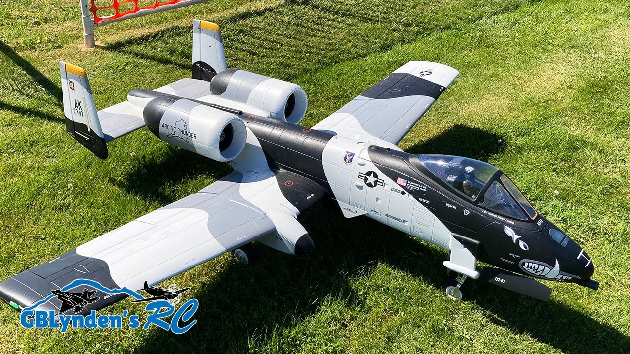
That's interesting, when I got mine a couple years ago no decals were on it and it came with a decal sheet with I think 3 different liveries. DId the Arctic Thunder so didn't use the decals anyway. This A-10 is exceptional and very easy to fly and land, but my only recommendation is do not fly it at the 78mm balance point they recommend. Way to nose heavy which will require more speed on landing, a harder time getting it slow with the nose up on landing and that's where many have landed nose wheel first causing the bucking bronco. I fly mine at 92-94mm and it slows down very nicely with full flaps and you can keep the nose up when landing. The jet wash from each fan goes directly over the top of the elevators, which exaggerate the effect when nose heavy requiring more up trim, but when flying slow, very little jet wash and it looses it's ability t to keep the nose up. If you balance it at least starting around 86mm and work your way back, when you cut the throttle it won't change attitude as much since it's more neutrally balanced. Just a thought.Leave a comment:
-
Hi All!
My son and I just received our new FW A-10. So excited to maiden after building.
I purchased from Motion RC and one thing I noticed is that our plane came with the Flying Tigers livery already applied and no decal sheet. Is this normal? There were no other signs that the plane had been previously owned, assembled or flown.
I’m ok with it since we were going to apply the Flying Tigers livery anyways and it saved us the time and hassle.
Thanks!Leave a comment:
-
This is Todd's Freewing A-10 Thunderbolt II Super Scale Twin 80mm EDF Jet also known as the Freewing A-10 Warthog.Leave a comment:
-
Thanks again for everyone's input. Box arrived majorly delayed, but nothing damaged. Going to use airbrush for a custom paint scheme (either Alaska or 100th Anniversary). As I was inspecting the parts I thought about painting the plane unassembled? Would that work or actually cause consistency issues of sorts?Leave a comment:
-
-
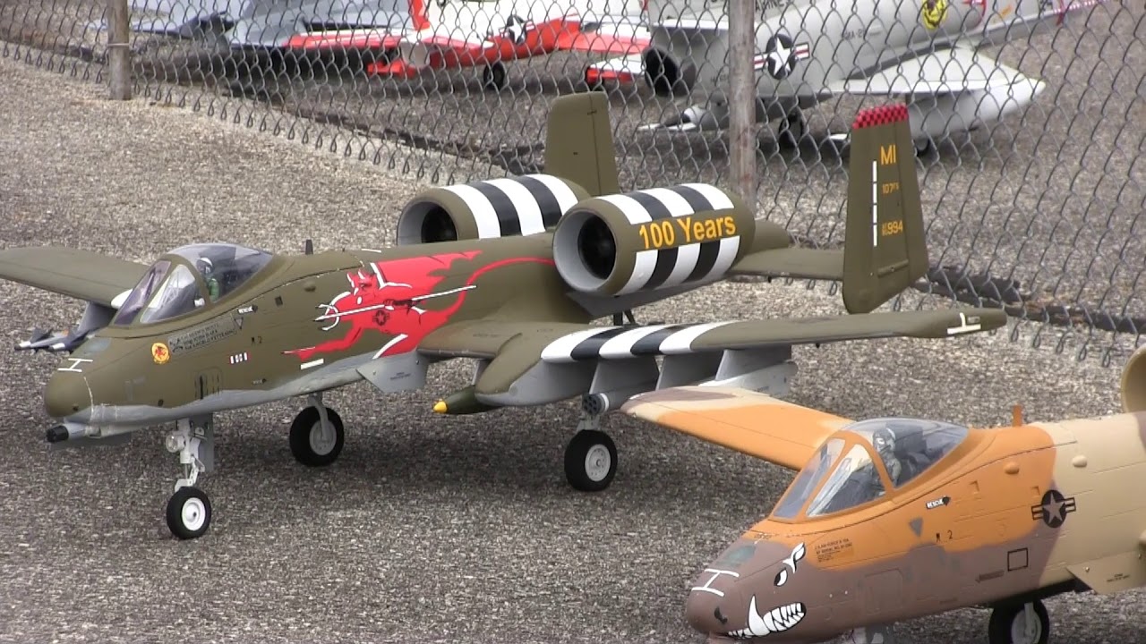
Ah I finally found the video. From 2019, before the pandemic. We need to do this again!!! Who is coming? Let's set a new record!
E-JETS AND E-WARBIRDS 2019 - YouTube
Leave a comment:
-






Leave a comment: