Callie Graphics

You must Sign-in or Register to post messages in the Hobby Squawk community
Registration is FREE and only takes a few moments

Register now

Announcement

Collapse
No announcement yet.

Official Freewing MiG-29 Fulcrum Twin 80mm Thread

Collapse
X
Collapse
First Prev Next Last
 
  • Filter
  • Time
  • Show
Clear All
new posts

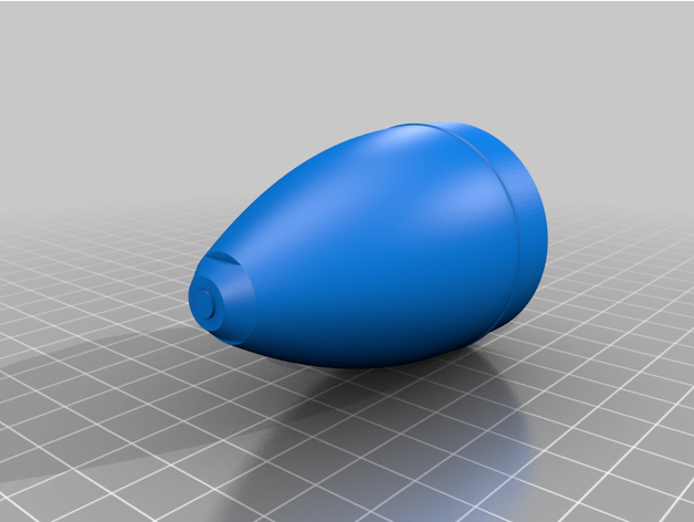
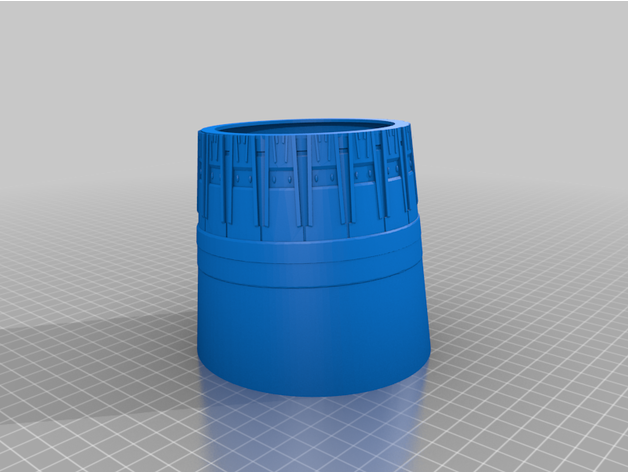
  • [QUOTE=Radar-Guy;n290242The files for the nozzle are available for a fee on cults 3d.In addition, I've uploaded a file for the ventral air scoop that was omitted by the designers of the model. This one is for free.[/QUOTE]

    RG, Absolutely phenomenal designs. Bravo Zulu, Sir and thank you. Best, LB
    I solemnly swear to "over-celebrate" the smallest of victories.
    ~Lucky B*st*rd~

    You'll never be good at something unless you're willing to suck at it first.
    ~Anonymous~

    AMA#116446

    Comment


    • Update 3D printing parts for Mig 29


      This is an upper and lower brace to better secure the front retract and its housing on the Freewing Mig 29. Bill of materials: Top plate (from this thing Retract plate (from this thing) 4-40 allthread (12in should be sufficient) 4-40 locknuts (x8) The parts should be printed at relatively high infill for maximum strength. Basic installation instructions (you'll figure it out!): Remove middle battery tray with 4 screws. Those screws are no longer needed. Remove second piece of plywood from battery area, which is secured to the retract housing with two screws. It's glued to the foam so might need some gentle prying. Press 4 locknuts into the provisions made in the retract plate Test fit and measure the length of 4-40 allthread you need, cut 4 identical sections. Make them a little longer than you think you need. you will likely need to enlarge the holes in the retract mount. Then just press the rod through the foam unil it pops out the top. Make sure it goes in straight! Thread rod into the locknuts which are pressed into the retract plate Place retract plate onto retract and insert the assembly. Trim threaded rod as needed - remember you will have a battery sitting on top of this, so make sure nothing protudes above the top plate! Remove battery strap from original tray and fit it to the top plate. Place top tray into position, making sure the threaded rods align with the holes in the plate. Replace two screws from the original lower plywood tray Secure locknuts into position on the threaded rod, and tighten the top plate down evenly. Grind down any excess threaded rod protuding from the upper locknuts - it's ok to have excess on the lower locknuts, so long as they dont interfere with the steering tiller.


      Basic mounting plate compatible with Freewing missile pylons (was specifically designed for the Freewing 80mm MiG-29). V3 set is tuned for better tab fit, flush surface


      Basic Freewing pylon (designed specifically for the MiG-29)


      I scaled and modified this from Dirty Dee (Chris Garca)'s design for the Freewing MiG 29, and I added a mounting rail and lug to fit the ArrowsRC wing. It is in several parts for ease of printing. I printed with 5% infill except for the lug, which needs to be solid. Print as light as possible if you intend to fly with it.


      This is a Russian R-73e heat seeking air 2 air missle and weapons pylon in 1/9 scale. They are suitable for the Freewing MIG-21 and MIG-29. The lower part of the missile is 240mm tall so it takes a larger printer. The missile and the pylon use the Freewing F-16 weapons mounting hardware. The MIG-21 in the photograph has a modified stock pylon that holds the fuel tank and the 3D printed one was added between that and the landing gear. I used epoxy to glue the missile parts and the attachments to the pylon.


      A 1:9 scale high explosives bomb to fit the Freewing Mig-29 dual 80mm EDF. Print parts, glue parts, paint parts. Accepts the standard freewing weapons mount (https://www.motionrc.com/products/freewing-f-16c-90mm-weapons-attachment-hardware) or print one of the ones available on here. Print with a single layer outline and 5% infill - it will be light and strong.


      https://cults3d.com/en/3d-model/vari...DkypmedJEd9wt4


      https://cults3d.com/en/3d-model/various/freewing-mig-29-ventral-air-scoop


      johnnyb

      Comment


      • One is missing:


        More to come soon...

        Frank

        Click image for larger version

Name:	0DD42C22-6627-4366-B2B3-D4F499088F06.jpeg
Views:	886
Size:	46.1 KB
ID:	290543

        Comment


        • Hello Frank,

          is there a chance that you would design a "brace" or "reinforcement piece" for the elevator mounts? I could chip in some money for the development costs.

          Cheers,
          Henrik

          Comment


          • Originally posted by Radar-Guy View Post
            do you have a reference picture showing where the ventral scoop is to be installed?

            great work!

            Comment


            • Quick question... anyone have a concern about the BEC not getting any cooling air over it? I don't see any way to keep it cool with it in the battery bays or nose. Feels like its getting pretty warm just sitting there powered up. Should I be concerned about this?

              Comment


              • Can someone print a set of the exhaust nozzles and sell them to guys like me who don't have a 3D printer?

                Comment


                • Originally posted by Dirty Dee View Post

                  do you have a reference picture showing where the ventral scoop is to be installed?

                  great work!
                  Thanks! Please see attached pic. Useful drawings are available here:


                  Click image for larger version

Name:	8DF3EC0A-CEA7-417E-A716-1DFFFC6F71B6.jpeg
Views:	918
Size:	100.8 KB
ID:	290640

                  Comment


                  • Originally posted by HK111 View Post
                    Hello Frank,

                    is there a chance that you would design a "brace" or "reinforcement piece" for the elevator mounts? I could chip in some money for the development costs.

                    Cheers,
                    Henrik
                    Servus Henrik,

                    Sorry, no. Based on my flights with the MiG and all the information available on various forums I don’t see a need for such parts (even with my 6,2 kW Wemotec upgrade). I’m currently repainting mine and I will follow the idea to insert some flat carbon strips parallel to the vertical stabs.

                    Frank

                    Comment


                    • Originally posted by Radar-Guy View Post
                      I will follow the idea to insert some flat carbon strips parallel to the vertical stabs.
                      That also should work, sure. Fair enough and thanks for the response.

                      Comment


                      • Originally posted by HK111 View Post
                        That also should work, sure. Fair enough and thanks for the response.
                        Hi Henrik - Some expressed concern about the plastic support box for the FFSs potentially separating from the foam after many, many flights. I added some 0.5 mm carbon planking to the bottom to address this. Also adds a bit of stiffening to this area.

                        Be sure to extend the front edge of the carbon enough to cover the front glue joint between the plastic box and foam.
                        -GG

                        Click image for larger version  Name:	56757A65-329B-4A1B-9B6E-33B2C78BD577.jpeg Views:	0 Size:	59.5 KB ID:	290647

                        Comment


                        • Originally posted by RC30Flyer View Post
                          Quick question... anyone have a concern about the BEC not getting any cooling air over it? I don't see any way to keep it cool with it in the battery bays or nose. Feels like its getting pretty warm just sitting there powered up. Should I be concerned about this?
                          Howdy RC30Flyer - I extended the BEC wire and hot glued it flat side down to the foam in the wing root area by the rear battery bay. So...only one side gets exposed to the air for cooling.

                          Commercial IC products recommended operating temp range is 0C to 70C (32F to 158F)....sometimes Tambient...sometimes Tcase. That’s a lot hotter than “warm”.

                          I flew mine almost continuously (not much delay between flights) on days when the free air temp was near 38C (100F), and I did touch the BEC periodically. It never felt “HOT”....only warm.

                          If you have concerns, hot glue it so it stands vertically on edge so air can get to both sides. That is about as good as you can do. I may also remount mine standing on edge so air can get to both sides before the coming summer heat. Or...You can always give it a cool down period between flights. Cooler is always better for electronics.

                          If you have serious concerns, you can buy a tiny brushless 5 volt case cooling fan to blow air over the BEC, but that may be going to the extreme.

                          -GG

                          Comment


                          • Originally posted by RC30Flyer View Post
                            Quick question... anyone have a concern about the BEC not getting any cooling air over it? I don't see any way to keep it cool with it in the battery bays or nose. Feels like its getting pretty warm just sitting there powered up. Should I be concerned about this?
                            The fact the battery bays have no vent holes should have been a concern to the designer. Poorly.thought out.

                            Comment


                            • Originally posted by leithalweapon View Post

                              The fact the battery bays have no vent holes should have been a concern to the designer. Poorly.thought out.
                              The fuselage is hollow aft of the aft battery bay and there are already openings into this hollow from the aft battery bay. Would it help to cut a hole in each intake tunnel forward of each fan that reaches into the hollow fuselage cavity? The canopy does not fit that tightly and should allow some air flow. Comments?

                              -GG

                              Comment


                              • I've not found external BECs to get "hot", even in the heat of the summer. It's the ESCs that can get hot and if it has a built in BEC, then it can get hot, too.

                                Comment


                                • Here's a file to print the "flare canister".


                                  Click image for larger version

Name:	Flare Container.jpg
Views:	758
Size:	70.0 KB
ID:	290763Click image for larger version

Name:	IMG_4297.jpg
Views:	739
Size:	88.2 KB
ID:	290764

                                  Comment


                                  • I know I'm being picky but the L and R on the stabs there really bug me.

                                    Comment


                                    • Originally posted by Evan D View Post
                                      I know I'm being picky but the L and R on the stabs there really bug me.
                                      Click image for larger version

Name:	20201103_045829.jpg
Views:	729
Size:	134.4 KB
ID:	290778
                                      BVM Bandit, EFlite Carbon Z T-28, EFlite Carbon Z Cub, EFlite Promethus, FW Avanti S, FW A-10 ThunderBolt, FW P-51 Mustang, EFlite Convergance, EFlite Carbon Z Cessna 150, EFlite Habu, EFlite Styker Q-F27, HSD Navy Super Viper

                                      Comment


                                      • Duct tape hides all.

                                        Comment


                                        • Originally posted by GliderGuy View Post

                                          Hi Henrik - Some expressed concern about the plastic support box for the FFSs potentially separating from the foam after many, many flights. I added some 0.5 mm carbon planking to the bottom to address this. Also adds a bit of stiffening to this area.

                                          Be sure to extend the front edge of the carbon enough to cover the front glue joint between the plastic box and foam.
                                          -GG
                                          Admittedly the ArrowsRC MiG29 is a lot smaller, but the way the FFS pivot supports are engineered on that model is significantly stiffer than on the FW MiG, without compromising the scale appearance. No doubt a bit heavier, but both models ended up nose heavy anyway.

                                          Comment

                                          Working...
                                          X