


The best thermal conductor comes when you tie it all in together, That is further facilitated by cooling directly the airgap with ferrofluid. Which will allow the core to truly radiate heat out from the bell.
-
Thermally Conductive Adhesives - Epoxies - Urethanes | Appli-Tec
For most true gamers its not a secret sauce Doc..... 😂Attached FilesComment
-
-
Hi Ralph
I see Christian is trying to help you understand the magnets which should be no issue if your motors produce their power at 70C the magnets should never be damaged in the first place.😏.
The truth is not premium in those assessments and we know that......based on the demagnetization..
"Hi, since the magnet still rules the Unknown Being,
a few notes on this.
A very simple way to see if all magnets are more or less the same is to apply a winding with thin wire to one of the stator teeth. Then drive the motor at a steady speed, using an oscilloscope to display the stresses that are induced. Okay, you need an oscillator, but when you have access to a thing like this, you can't just look at the voltages and their value. The curve shape also allows some conclusions to be drawn about the type of magnetization.
The second method is to compare the magnets before they are glued in place and to detect slipping. To do this, you need a compass and a longer wooden top, table ect. . To determine, the compass is placed at one end of the plate. Then you push one of the magnets on the plate, starting with the greatest distance to the compass towards the compass, align the plate with the compass so that the compass needle does not point in the direction of the magunet, but 90 degrees towards it. As soon as the compass needle turns towards the magnet, mark the distance on the board. Repeat this with all the other magnets and you can see if one of the magnets has been pushed much closer to the compass or if the needle has already moved further away. Closer, weaker magnet, farther away, stronger magnet.
The proposed method with the current clamp , from the Aloys is very suitable. You can also wrap a few turns around one of the clamp bars and set a current that works against the permanent magnetic field, but you need a well-stabilized power supply for comparison measurements.
Unfortunately, you can't always assume that all of the magnets have been magnetized exactly 90 degrees by the thickness of the magnets. Such angular errors interfere with the induction in the coils. However, you can also use the magnetization direction for the motor. In other words, if the actuator creates a rectangular block commutation, a wider magnetization will be less lossy. This is done by side-by-side magnetic strips at a distance from each other.
Magnets can be magnetized in such a way that the field lines to the center of a magnetic pole become more concentrated, amplified. This makes sense, as it increases the peak induction voltage. Then it needs fewer turns with then thicker wire, less resistance. In slot racing, we glued the magnetic poles together from several strips in order to concentrate the maximum flow on the respective stator tooth.
In order to design the field in such a way that a larger air gap is bridged, flux wedges and half-axis magnet arrays are best suited. On the one hand, the magnetic flux is concentrated, amplified = requires fewer turns with thicker wire, but also needs thicker stator teeth to be able to conduct more flow.
The second effect is that the magnetic losses in the stator plates are reduced. In the case of very small lift gaps, very high-quality sheet metal qualities are also required, with larger air gaps, not quite as high-quality sheet metal qualities have to be used.
The magnetic inference in the bell improves when the magnetic strips are in grooves. Alternatively, you can also glue iron sheet strips in the bell between the magnetic strips, sheet thickness 1/6 of the magnetic strip thickness.
Happy Amps Christian"
"The unknown being"..... LOL thats funny.
Attached FilesComment
-
-
Ralph you need to ask Christian does the iron strips increase the reluctance and how similar would this be to a PM assisted SRM.Comment
-
Hello, I already did the A-B test in October, but I didn't want to report about it here, otherwise I would have already written about the interesting result. This is also due to the usual tone of how the big boy treats his subjects and it even adds to the amusement, thank you I don't have to give myself that here.
~Audiosmith~
Hi Ralph
I don't get it. Is it trouble in paradise on the German social media? Isn't he one of your subjects saying this? I took a count of the thumbs up in all your threads.This declaration from him doesn't sound flattering but are you not using his estimates vs the accepted fusing values for the conductors? These conductors also have ampacity ratings.
Regards
HubertComment
-

Powercroco
UserSince I don't have any use for such a motor and won't have one for the foreseeable future and I don't feel like winding the thing anymore, I put the one remaining prototype kit for a 24N20P HK 7465 in the stock market today.
Maybe there is someone who would like to wind up such a water-cooled approx. 20-25kW car according to his own idea and build it himself.
A few pictures can be found here in the thread and various data from the little brother on the MHZ website.
Scorpion HK-7455-330KV |22,4KW | Water-cooled | Outrunner | 2137-W
Exclusive special series of the popular Scorpion motors In close cooperation with Scorpion Motors, this series of water-cooled external rotor motors was created exclusively for us. The advantages at a glance External rotor motor with higher efficiency...
 www.mhz-powerboats.com
With the extreme length of the bell, the use of the intended counter bearing (the corresponding shaft stub at the end of the bell is available) is absolutely mandatory in my opinion, despite the 12 mm shaft.
Appendixes 100_0952.jpg 313.4 KB · Views: 19
Last edited: Yesterday at 02:53 PM
VG
Ralph
powerditto.de
Audiosmith
UserWell, when I wanted it, it was supposed to be in your moped, now I got a Lehner 7065 for my kart and in retrospect I'm happy about it.
It has a 15mm shaft and a full steel bell, so it is mechanically more stable and also much better in terms of workmanship.
There are no tendencies for the bell to wobble due to the 12mm shaft and too thin bell base and it can be operated optimally on a professional FOC ESC.
Powercroco
UserJou, then you've done everything right this time and don't have to bother with junk!
VG
Ralph
Dang Borat, Yall like that now ????
Wirst du ihn also wieder von deinen Flugveranstaltungen im Hinterhof verbannen? Das wird so cool, dann kannst du Kai den unfairen Vorteil gegenüber Christian Hidde verschaffen... Du könntest dann gewinnen.

YT
Hubert
Attached FilesComment
-
Now I let myself be persuaded to build the 7465.
I couldn't resist the prospect of a nice contribution to my charity.
This time, however, the speed for 16S is said to be significantly lower.
It should only be about half the speed - which should result in a reduction of the forces deflecting the bell to 25%.
Probably the 12 wave will not cause any more problems then.
Nevertheless, I will definitely thicken the bell bottom (this time only a little) - the method has already proven itself in the past with other engines.
In addition, I am thinking about preventing the shaft
from bending by means of 3001 bearings. The less than 10€ additional costs don't matter with such a monster anyway.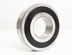
3001 2RS (Double-row angular contact ball bearing / old 3001-B-2RS-TVH)
3001 2RS / 3001-B-2RS-TVH angular contact ball bearing 12x28x12 mm (ball bearing 28x12x12 mm) - Double-row angular contact bearing 3001RS.
www.kugellager-shop.net
Perhaps these two measures alone would be enough to make the part fit for jet speed.
But that's definitely not my job.
Appendixes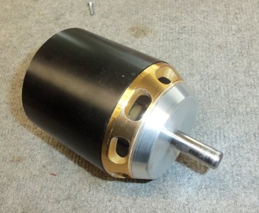 100_2120.jpg 550.4 KB · Views: 8
VG
Ralph
powerditto.de
Attached FilesComment
-
Hmm I dont get your bearing selection "Dr Ralph". The bell/rotor forces you talk about are radial so what does the angular contact bearing improve .? Their claim to fame is axial thrust support.. What you should be looking at is a full compliment deep groove radial bearing. One with SiC balls would be a bearing advancement in the right direction.. If the bearing you posted on the German social media is only 10 euro more than the standard NMB it isnt much there to get hyped about. A real upgrade in bearing may run upward of 200 dollars USD. A yard for each bearing and you never buy just one or two in the first place.
Do you know how to properly disassemble and clean a ball bearing "Dr Ralph"? Old medicine and electric motor mechanics are a totally different beast.
Did you and your friends on the German social media know that ferrofluid by its nature helps maintain air gap stability and concentricity in linear motors?. Also the 14 pole motor is a quieter machine and has more balanced modal forces on the stator. So you should make it a 14 pole if you truly are doing your homework.
enjoy the dialy winders news Ralph
YWIA and thanks for stopping in. maybe you reply one day....
YT,
HubertAttached FilesComment
-
-
Its funny "DR" because I told you well over 6 years ago the NMB bearings were a bare minimum in bearings and could use improvement. Wonder if you recall what you posted then. Its still on Heli freaks all these years later. Most mechanical engineers that have had even and iota of exposure to bearing tech knows the best bearings are swiss made....🙈 A full compliment bearing would not have a retainer like the scorpion factory posted here and it would contain nearly double the balls. its going to be a faster bearing too when you select it correctly. If its sic or ceramic it also wouldn't transmit triplen currents through the shaft. That also improves the magnetic and electrical circuit performance..
In addition to its mechanical failings you detailed on the German social media Its a fact that companies like Lehner and Neu use much better bearings in their motors than scorpion...
Enjoy life.....
YWIA
HubertComment
-
Powercroco
UserVery interesting link, thanks for that!
Of course, as a 2308, it's not particularly hard to look good against a 2207.
Even with the same weight, the longer lever arm and lower density will generate a certain advantage.
It's the same as always, you have to keep an eye on every detail and measure everything yourself, otherwise you can easily get caught up in various advertisements or deceptions.
It's exactly the same as when various experts make a comparative judgement about the workmanship of a certain engine, without ever having had it in their hands, let alone being able to fall back on their own measurement results.
But that's apparently normal these days. VG
Ralph
powerditto.de
Hi Borat
Its funny you posted this in the German social media. You speak from experience because you have done that very type of false promotion across all the American forums for years. You telll them the motors run cool and the bifilar winds produce less ac noise. Clearly none of thats true. 180C is what kills the magnets so the proof is in your pudding. Remember how you skewed the results with Lehner with a 2 s lipo run when the application would never run it there and the higher rpm would show where the motor lacks, You run it close to dc (slow rotator) to avoid all the electrical noise it makes at the applicable voltage idle speed ., The only thing im impressed with is how elaborate the setup is to deceive everyone. Currently you trolling Thomas with the post about his tmotor that out performs your rewound scoprpions produced this 2slipo test and vanished for 3 months without a post when i called it out.the fact that the number point to 2 s lipo and you both tried to lie and say it was a higher voltage but George Ohms caught u. Now the same people are posting scorpion is of low quality.
Audiosmith
User
31. January 2024
Well, when I wanted it, it was supposed to be in your moped, now I got a Lehner 7065 for my kart and in retrospect I'm happy about it.
It has a 15mm shaft and a full steel bell, so it is mechanically more stable and also much better in terms of workmanship.
There are no tendencies for the bell to wobble due to 12mm shaft and too thin bell base and it can be operated optimally on a professional FOC ESC.
Ill be glad when the Americans realize the discrepancies in your post versus what their eys see. Does this look like the result of cool running ?
Comment
-
powercroco
Registered Users
Join Date: Oct 2011
since I build motors only for use, my point of view has changed - away from all these based on several theoretic possible improvements.
we run our speedplanes full throttle all the time and we have less than 60 sec untill the battery is empty.
5% more eff. would mean 3sec more runtime.
we have about 3 or max. 4 flights through the meassuerement system into these 60sec.
so 5% arn't important for us.
important is "only" a thermically stabil drive system, good propeller and very good pilot.
in every motor we found an rpm area, where the esc frequency and the motor resonance frequency seem to come together. to use the drive at these rpm, will destroy the motor be throwing away the magnets.
this is more important in 14P than in 10P motors.
Or maybe this one proves how cool they run if the damaged magnets dont.. I don't know why you are posting in his thread. Other than you are trying to discredit the better motor. Scorpions are of average construction and elevated cost. They can thank you and the charity dog $helter for that. And 600 dollar 42 mm motors Even though there are new proven winds you have chosen bifilar stranding with no twist Parallel pseudo Bi filar stranding hardly improves the electrical performance of the machine. They dont run at stall! And truly the thumpers is not a 'bifilar winding' anyway. A slight Increased lever arms i dont see any real advantage because it also takes more to start and brake it.. All those percentages of change of dimension is great but worthless as you have made no correlations to performance based of those percentages of geometric change. You dont think a wind improves anything in reality but you think 2.2% increase in diameter does without a single performance measurement to confirm that in the real world. What happened to the great empiricist POWERCROCO that doesn't buy the theories of the IEEE?
Man that's outstanding...
🙈🙉🙊
I assume that my response is what you are here looking for at 2:59 am.Attached FilesComment
-
-
Youve done things like take measurements at zero degrees timing to bolster eta but you actually run at greater than 18 degrees timing. That changes the eta dramatically and most of these hobbyist dont know when you are feeding them BS. Heavy loads like heavy timing so u know a speed plane motor will never see o degrees timing. Thats called a lie my boy. . Extremely deceitful and misleading.to all the forums and perspective consumers. Evenb with 0 timing you still came out lower than a machine running only 10 degrees which is pretty standard as a medium timing. You told them a YGE 320 can run at 48khz another lie they do 16khz and that's it. . You do things like implore DZHAMEL to not post the tru APD log data when the world knows it a better controller. Because of the BS you and incompetent set up hobbyist false reports APD has pulled the inverters from hobbyist shelves!!! Now you are left with a cheaper antiquated dumm YGE 320 so good luck. Your main hobby is lying to the forums about your motors and equipment gifted to you from companies like . Young generation electronics. It's them than confirmed for me personally that the post about a YGE 320 running 48khz is bs. But ne one capable or reading specs for themselves can easily see that was false.

YT
Hubert
The real 1BOHOComment
-

YGE Service
From:service@yge.de
To:hubert
Mon, Feb 27, 2023 at 7:47 AM
Hello,
do you mean the PWM frequency?
The PWM-frequency of the 320HV is adjustable with the ProgCard from 8kHz to 16 kHz.
The Opto 255 has an automatic PWM-Frequency which works between 18kHz and 40kHz.
Mit freundlichen Grüßen / Best Regards
Herr Marian Waßmuth
YGE - Service
Otto-Hahn-Str. 1A
49134 Wallenhorst
Germany
www.yge.de
Tel.: 05407 / 8034701
Dienstag & Donnerstag
13:30 bis 16:30 Uhr
Do you see Powrecroco how you and ya friends on the German social media lie all the time on the forums? I know what you ALL have done very well for the last 12 years on the American forums. Jerk them...
and of course a consortium of dishonest modelers cannot get along for half a day.
Astonishing level at T-Motor F40 V | RC-Network.de
The "Scorpion Knockers" | RC-Network.de
Lehner 4125/4140 | RC-Network.de
and this one is 4 years old and the stator is still bare from the "Leaders"
Prototyp 12n14p YD | RC-Network.de

You have not implemented a single thing new in at least 4 years. Scorpion as a company goes in a different direction than you with the a series 14 poles and axial cooling in a much lighter package for a plane. They also build a Tribunis which is more capable than a YGE 320
I cant wait to see idle speed FFT captures on a scope from Louis Fourdan, It may not ever come now since you all are aware I'm here to interpret that data and derive the motors power factor and Thd for the inexperienced hobbyist that dont own or use scopes.
Your camp definitely doesn't like me...😁Comment
-
Powercroco
UserUnfortunately, the 2-row bearings only start with sizes that could not be accommodated in a 5060.
Have any of you ever built with something like this?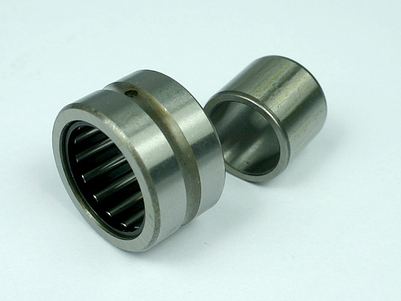
Needle Roller Bearing NKI-10/20
Needle roller bearing NKI-10/20 . Dimensions: 10 x 22 x 20 mm needle roller bearing with inner ring
 www.sturm-kugellager-shop.de
The part has an inner ring and is intended for a 10 shaft.
This should reliably prevent any deflection of the shaft between the bearings without taking up too much installation space.
Unfortunately, I can no longer find the FEM, where an expert had once shown how large the deflection between 2 normal ball bearings can become, especially with long motors with one-sided bell load at high speeds.
At that time, the discussion had ended with the recommendation of a carbide shaft that could not be found. And certainly not with threads attached.
The axial load in propeller operation is already absorbed by the rear bearing alone.
After all, there is no need for a speeder-like operating time.
What would you have to pay particular attention to if you wanted to install something like that?
VG
Ralph
powerditto.de
Hi and why are you asking them when its clear they dont know. If they did the first thing they would point out is what I have . If radial loads are the issue and you clearly restated that in the post why in the world would you be looking at an angular contact bearing. Dr Ralph, It makes zero sense.Comment
-
Quote:"I was thinking Ralph that in my sport 15 seconds is alot of time. An entire lap. Will people pay to have another full power lap through the finish line? Absolutely. Looking at the cash they burn already.Originally Posted by powercroco 
here we are at the point: what is "much"?
noone can come out of the dependences of the often shown "over all losses" diagramm.
if all "other losses" without "copper losses" at the point of work are only 1-2% you cannot generate a difference, what is high enough to meassure it clean with our instruments.
also
P in = volts * amps
P out = torque * rpm
in combination with:
p out = P in * efficiency
shows clearly, that there is no much room for improvement anymore under the given conditions.
the most important thing in modeling:
to get 5% better efficiency (really impossible at the point we reached) will give someone only 5% more battery duration.
instead off 300sec you will get 315sec flighttime.
and these 15sec more will double the price of the motor.......
and one more thing:
a lot of these new ideas bring a meassurable win in big motors, but we never have been able to "scale" these effects down to our motorsizes.
For Thd measurements would typically only look to the 50th harmonic so for 1k that would be out to 50khz, over double the highest audible. There is also still reason in my reading to use an insulated bearing. Non insulated can carry the triplen harmonic currents. If the steel shafts are not expanding from heat I see no reason you wouldn't be able to use a full ceramic. It is stronger, has less drag, and is electrically insulated."
HubertComment
-
 02-28-2016, 04:59 PM
#52 (permalink) 1BOHO
Registered Users
Thread Starter
Join Date: May 2014
Location: Research Triangle Park
Thanks for sharing. Will definitely keep in the notes...
BTW
Full compliment all ceramic bearings in a 19x10x5mm are upwards of $160.00 usd a pair. Maybe I'll ask for a working sample for test......
Without a single more manufacturing process that alone would literally double the price of this motor. Would it yield anything in efficiency if PO=torque*rpm. Suppose you happen to get consistently more rpm and triplen current insulation from their use.Then maybe it would. What did your bearing test show in this regard? and did you test full ceramics? Attached Thumbnails


Comment
-
and so the foum can see this is hardly new and youve already been told this in 2016 8 years ago. When I asked what test you ran and what they showed there was no reply. If you are a motor expert as they believe why do you need a lesson on ball bearings over and over again? Ive even told you the proper way to select bearings and how to check them for true roundness
you see the 2.7khz triplen peak right here on a Hk SL5020 at 300 hz fundamentalComment
-
Radikale Konzepte und praktische verifizierungen inspiriert durch Wick_3 Thread - Seite 5 - Motoren - RCLine Forum
This was 2015 🙈
sad thing with you is you forget our history
Comment
-
Needle bearings are also no ideal for this type of thing and will only drive efficiency down with their drag as the wouldn't be lubricated as they would be in a crankcase and fuel with oil.in it.
The boys dont know anything about needle bearings or how to make them as well as the proper material selection. I have all those prints to double window roller than can do 30,000 rpm in .90 nitro. Let me see you find a needle bearing anywhere in the world like this... Search all the German social media .or see if you can pull it off with the dirty lathe.
For the last month I have continued to investigate the possibilities of bottom end roller assemblies that would be used in 15 to 30 cc two cycle engines. These assemblies must be able to operate in the 22,000 to 28,000 RPM range, at 7.5 to 9.5 HP, with absolute mechanical reliability.
The tools shown in the first photo, as well as the holding fixture mounted onto the Brown & Sharp's solid tapered center, are required to machine the 14 slots in the retainers .5470" OD. The slots are 25.714* apart. A calculation is made of the width of the retainer's pie shaped piece between each .0787" wide slot, measured at the roller's center line. This dimension is approximately .027". The following calculation is made to determine which dividing plate is needed to give 14 divisions of 360*. Since the dividing head is geared 40 to 1, 40 is divided by 14 which equals 2 12/14 = 2 6/7 = 2 42/49. This means that for the indexing of 14 slots, each 25.714* apart, the dividing head is rotated 2 turns (18*) plus 42 holes (7.714*) on a 49 hole plate. The dividing head is rotated an additional 2 holes to give .001"+ clearance (.0797") for each roller in it's slot. Again the 40 to 1 gear ratio means that one complete rotation must equal 9*. Using a 49 hole plate means that each hole equals 9* divided by 49 or .1836* (11 minutes). Therefore, two holes on the 49 hole plate equals .3672* (22 minutes). This is sufficient to give the necessary .001"+ clearance in each slot.
The dividing head repeats accurately because there is no vernier scale to read. The spring loaded tapered pin must drop in it's hole for indexing amounts. The two photos before the last two show how easy it is to index & open the slot for the .001"+ clearance.
The last two photos show how the machined sleeve is mounted & located precisely for machining. By using a solid aluminum mandrel inside, which is located in the holding fixture, there are no burrs to be removed on the ID of the retainer after machining. Tumbling removes any burrs on the retainer's OD. The sample roller & the gauge pin act as go-no go gauges for slot measurements.
Jim AllenAttached FilesComment
-
-
I would like to share continuing developments concerning the building of very high speed bottom end roller assemblies that would be used in miniature very high performance two cycle engines. Retainers of this design type have been successfully used in engine's operating in the 30,000+ RPM range.
The precision machined retainers shown in the photos are the result of in depth designing & testing. The unique mechanical design (two rollers in each window instead of one) gives a retainer which has a very high load carrying ability, with no loss of limiting RPM, compared to a stock retainer. This happens because the two roller window design increases the standard roller count of 10 rollers, for the retainer's size pictured, to 16 rollers. There is no problem with rubbing friction even though two rollers in each window are in direct line contact with each other. Heat that is normally associated with roller assemblies is a result of the friction caused by roller skewing & roller skidding. The precision machined roller cages shown in the photos totally eliminate roller skewing because the rollers are guided along their center lines from end to end. This type of roller guidance is not possible with any type of snap in type roller cage design! Roller skidding is also greatly reduced because the retainer has very low mass & therefore very low inertia. The metallurgy used is a martensitic, precipitation aging, cobalt strengthened, 18% nickel maraging steel. With a simple heat treatment of 900* F for 6 hours, the C-350 maraging steel reaches an ultimate tensile of 350,000 psi at Rc 60. Some of the special characteristics of this steel would be it's high toughness, ductility, impact, compressive (388,000 psi) & fatigue strengths. The steel is resistance to crack propagation, is easily machined, has minimal distortion, predictable shrinkage & is free of decarburization during heat treatment.
Typical applications for maraging steels which began to appear in the 1960's are guided missile & rocket motor cases, wind tunnel models, recoil springs, landing gear components, high performance shafting, gears & fasteners. Prototype retainers are machined with the modified Brown & Sharpe #1 dividing head shown in the last photos. Fixtures, similar to the type shown, are directly mounted to the Brown & Sharpe's #5 taper dead center. The tapered dead center has been modified with a draw bar & is concentric within .0002".
Jim Allen
This is one American ME's take on the subject matter where is the German social media on this? Were curious what the "leaders" have to show us in bearing tech.
Attached FilesComment
-

Comment