-
OOPS!
Thermally conductive adhesive ties the layers together thermally.
And look another winder in Germany post that charred windings is not part of his winding program....

Thanks for your time an patience
HubertComment
-
These people aren't honest with you because how would the EQUIVALENT single layer and dual layer have different resistance with wire the same length.
The inductance would be different but the resistance would not.

See what im talking about.....🙈🙉🙊 there test also tells you nothing because you really have no business running a single layer with a blac drive.
I already caught this one with a bogus 2 s lipo test to compare the scorpion and LMT 41 and a report a yge 320 does 48 kHZ .
A big fib...
TTYL
HubertComment
-
The amateurs should run a real test with the single layer LMT and ralphs dual layer scorpion. Run them both to desynchronization and see which one gives up first.Comment
-
We all agree many inductors and transformers have more than one level of wire wrapped around the iron.....😶
Inductor potting and testing
The inductors used in this study were made from Micrometals T400-61D high-temperature, magnetic-powder toroid cores wrapped with 62 turns of 10-gauge insulated copper wire, which yield about 500 μH inductance at load. Inductors were potted in custom-made aluminum cooling plates fitted with liquid inlet and outlet ports for connection to an external circulating fluid bath. The five different materials were used to pot three inductors with each material, resulting in a total of 15 potted inductors.
Before potting, each inductor was fitted with a thermocouple to measure its temperature. The location of the thermocouple corresponds to the hottest location in the inductor as judged qualitatively from a thermal camera image of an unpotted inductor under load.
For the thermal tests, each inductor was connected to a Manzanita Micro PFC40X-188 charger passing 9.3 kW and 40 A at 240V input with 0.98 power factor. The power at the inductor was 30W. The aluminum cooling plate was connected to a temperature-controlled liquid bath; each inductor was tested at coolant temperature set points of 25°C, and the typical automotive coolant temperature of 50°C. A second thermocouple was attached to the exterior of the cooling plate to monitor temperature changes during the test; however, the temperature rise of the cooling plate was less than 2°C, even in the most extreme cases.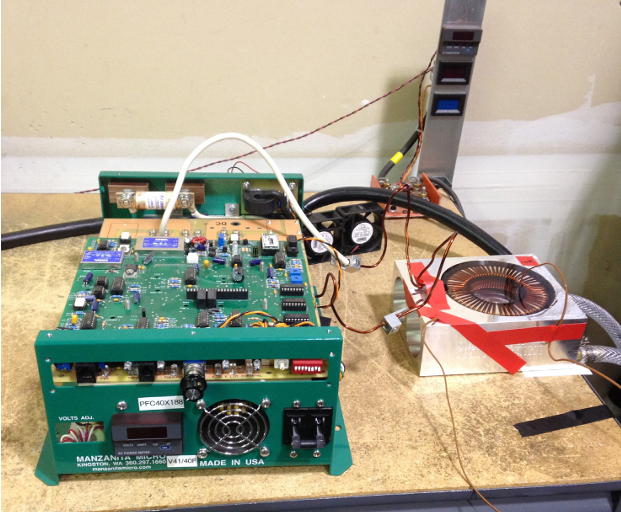
During each thermal test, the temperatures of the inductor and cooling plate were recorded using an Omega Soft data logger. The cooling plate and inductor temperatures were allowed to stabilize with no power. Power was then applied, and the temperature was monitored until the inductor temperature stabilized. The equilibration time was chosen at the point when the temperature reached a steady state (i.e., no further temperature increase took place), and the reported temperature rise was calculated as the final temperature of the inductor minus the initial temperature.
Results
During the study, they used five of their silicone potting materials and tested 15 inductors at least once with several tested multiple times to determine repeatability. Error bars are plus and minus one standard deviation of the data, which includes part-to-part variation and repeatability.
The data show that both the inductor temperature rise, and the equilibration time are independent of the coolant temperature, as the data at 25°C and 50°C are nearly superimposable and within the test variation. It is important to note that the variation becomes much smaller as the thermal conductivity increases due to the more effective thermal connection to the aluminum cooling plate.
Comparing an inductor potted with an insulating material (0.1 W/m∙K) to the most conductive material (4.0 W/m∙K), the heat rise is decreased by about 50°C, and the time required to reach a stable temperature is decreased from nearly two hours to 15 minutes. These significant improvements in heat management enable the development of significantly smaller power electronics.
Dramatic reductions in both temperature rise and equilibration time are observed for inductors potted with thermally conductive materials. The average temperature rise with Parker Lord’s Thermoset SC-400 encapsulant was about 55°C, and the average rise for the company’s most thermally conductive materials, CoolTherm SC-320 and SC-324 encapsulants, was less than 10°C. Even the moderately conductive silicones, CoolTherm SC-305 and SC-309 encapsulants at 0.7 and 1.0 W/m∙K, respectively, provided significant improvements.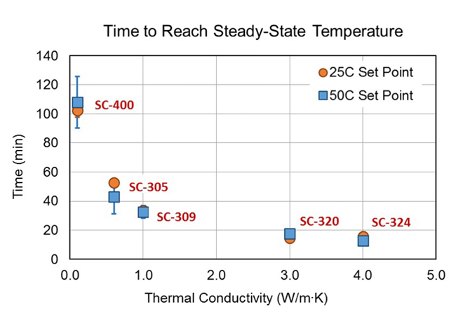
Under different test conditions that would generate a temperature rise much greater than 55°C, the improvement would likely be even more pronounced. Similarly, the equilibration time was also dramatically reduced with the higher thermally conductive materials. With the non-conductive silicone, Thermoset SC-400 encapsulant, nearly two hours was required to reach a steady state, whereas a stable temperature was achieved in less than 20 minutes for CoolTherm SC-320 and SC-324 encapsulants.
This rapid temperature recovery means that heat is dissipated quickly, and components will spend less time at elevated temperatures, thus increasing the lifetime of the components.
Conclusions
Proper thermal management is essential for developing power electronics that are smaller and lighter. And smaller and lighter means higher power density. As the study proves, using thermal management materials provides the unique combination of high thermal conductivity and low viscosity as well as substantial reductions in both maximum temperature rise and the time to reach a stable temperature. Both benefits bring about improvements in efficiency and component lifetime, thereby enabling high-performance power electronics.
Parker Lord’s team, comprised of seasoned technical support and application engineers, is prepared to assist you throughout your power electronic design process. Their vast experience includes working with electric vehicle OEMs and battery companies on cutting-edge technology. However, their scope extends beyond batteries. They are committed to ensuring that power electronics – including inverters, converters, and e-motors – function safely, reliably and efficiently by implementing effective thermal management strategies.
If you’d like to learn more about solutions for power electronics, please reach out to their team.
To read the whitepaper, “Thermally Conductive Potting Compounds Enable Higher Power Density Electronics,” visit their page to download it now.

Hubert
Comment
-
For me its time to move on. We run the coolest and most efficient here.
TTYL
HubertComment
-
Christian Lucas
UserHi,
the most optimal winding has flat sheets that lie flat to create as few proximity effects as possible. Upright has the greatest proximity losses and with the method you use of two adjacent windings of a phase, these losses are greatest with opposite currents where the conductors are energized in opposite directions. All thick wire is obsolete because of the losses. Several thinner conductors slightly twisted, as Hubert has already shown, are much better.
Happy Amps Christian
Happy Amp ́s Christian
GO FAST TURN RIGHT AND GET OUT OF MY WAY

Powercroco
UserWhat has your Hubert shown so far, except that an unencapsulated Align 700 with little iron in the hammer handles and YY thick wire winding, easily outperforms all other motors (including the 41 L outrunner) in efficiency and load capacity.
Or did I overlook something at the time, Mr. Mechanical Engineer FH?

Last edited: 11 minutes ago
VG Ralph
__________________________________________________ __________________________________________________ _______________________
Never feed a black troll!
Audiosmith
UserThe winding still has a healthy face color and still works, it is possible that the iron pig got so warm because it had a mechanical problem and therefore ended up with you for repair, as I had suggested.
Otherwise, there is no perfect single-layer winding if you want to achieve a proper filling degree, because the winding room is like a piece of cake and that can only be filled perfectly in two layers, single-layer inevitably results in an air motor.
Comment
-
And so now Americans we know who is here reading OK?Comment
-
And also that Ralph is wrong and did miss something My align he still talks about is encapsulated and not with endfest...but with high temp epoxy that does have a higher TC than endfest.

Ralph you don't know what you are talking about.....
Thanks for your time and patience
HubertComment
-
Thomas is also wrong you can always fit more wire in the single layer the rotor has to have room for tall heads. U2 are making a real mess of things and the claims are incorrect. The IEEE and about 70 universities across the world have already studied all these things in great detail.
Get ready for 2025 speed masters don't worry about the us....
Ralph talks too much he knows it all and turned down a pyro to fit large wire when the skirt is already removable...

Thanks again for your time and patience
HubertComment
-
Dont use my align in your lies Ralph. I've told you time and time again the bifilar was wrong and no more than 2 strands of mono would benefit a large untwisted axial lay. A YY or delta is already that 2 strands. If you're into large mono why are you winding a bifilar which equate to at least 4 l smaller straight parallel strands to the inverter. I don't run anything like that and the Align certainly is not. It is a YY LRK which means 2 strands per motor terminal like Dr Dorell's paper would suggest. I've showed you the diagrams a millions times and when you get caught you make up **** just like now.
It would be less proximity loss to just wind a 12 AWG or 11 AWG ( 2.305mm) YY or Delta. Below 500Hz and to stall skin will be negligible as far as I'm concerned..
That bifilar with untwisted wire is noisy nonsense.
all you have to do to clean up the single layer is run dual inverters or slot wedges,Attached FilesComment
-
-
What Hubert has told you is to wind a 3 or 4 layer hybrid and that will tune down all those losses and allow you to start refitting to the largest wire you can make work. This is How EVs use large harpins and negate skin and proximity losses in the large welded coils.
Revisit the Gerling/Gurakuq but you wont listen until I show you how.

TTYL
HubertComment
-
Kinda silly too.. The air you see present in single layer is also there in the dual layer hidden between the wires which make it alot easier to have a thermal resistor of air trapped between the wires than around them.Comment
-
Kinda silly too.. The air you see present in single layer is also there in the equivalent dual layer hidden between the wires which make it alot easier to have a thermal resistor of air trapped between the wires than air flowing around them. The other issue is you dont understand what makes one inductor better than another. It has already been shown the single layer generates more torque for the same amperage so it doesn't need as much to do the same job as a dual layer in the first place. The issue is a rotor and subharmonic issue. It has zero to do with the resistance of the wire between the two machines which would be equivalent if they are wound equally with the same diameter wire.
DUH!Comment
-
I will be happy later to show you a more detailed study on TC adhesives on motors and what was discovered a bit later.Comment
-
- Created onYesterday at 21:32
- Christian Lucas
Hi,
just because the windings that are wound by hand cannot give off the heat optimally, stators have been designed whose winding groove filling is inserted. The heat is dissipated into the stator by the groove-filling, highly thermally conductive potting, which, depending on the performance design, has fine to larger bores through which coolant flows.
As a result, the coils do not heat up to critical areas in the first place. Even in the case of utopian overcurrents, the power loss is dissipated from the winding and stator. As with the model engines, the short boost power is realized as continuous power and the booster power is twice as high. In addition, there are optimized for cobal iron: calculated stator sections, which have much more iron in the coil, and of course magnetic systems that generate flux compression to provide the necessary magnetic field.
The heat loss is drawn laterally from the winding groove into the winding heads by very good thermal conductivity of copper, where it can be dissipated best, the copper that generates electromagnetic force should be present in the groove with a maximum filling factor.
As usual, the winding head is cooled directly by proper air flow, even better by liquid cooling or by a thermally highly conductive potting compound on motor structures that are close to the winding heads, housings made of aluminum or CFC. Alluminium because of the more than double the heat capacity compared to copper and CFC because of the thermal conductivity when the right fibers are used.
Phase change cooling is something if there is no other cooling option and the lost energy is to be stored temporarily. In 1995, I helped develop and test such materials with SGL as part of fuel cell development. For example, we have equipped the apron hub engines of the Airbus A320 with it, which have absorbed the entire energy lost for the journey from the gate to the runway, in order to then regenerate them for the next landing and take-off when they reach high altitude and thus cool air layers. These were phase change materials that have a very high thermal conductivity with a very high graphite content, executed as liquids, pastes and solid plates.
So high heat: Conductive potting compounds are indispensable when used correctly. As Hubert from the United States has also shown in his latest tuning projects, the motors run much cooler even in the winding design shown here, achieve higher efficiencies as expected and require much lower amounts of energy from the battery. The great pictures are thus obsolete, so the statement of the winding caster was taken ad absurdum. For the bin. Even ChatGPT knows better:
High thermal conductivity vacuum winding potting in electric motors offers several advantages:
1. **Improved heat dissipation**:
- Encapsulation with a high thermal conductivity material improves heat dissipation from the windings to the environment. This reduces the operating temperature of the windings and increases the efficiency and service life of the motor.
2. **Reduction of Hot Spots**:
- Local overheating or "hot spots" can be reduced by a more even distribution of heat in the engine. The potting material helps to distribute heat more evenly and avoid hot spots.
3. **Increasing mechanical stability**:
- Potting mechanically protects the windings by fixing them and protecting them from vibration and mechanical stress. This can improve the durability and reliability of the engine.
4. **Environmental Protection**:
- The potting material provides protection against moisture, dust, chemical agents and other environmental factors that could damage the windings or affect their performance.
5. **Reduction of Partial Discharges**:
- The potting can prevent the formation of partial discharges, which can be caused by air pockets or irregularities in the winding. This increases the electrical insulation strength and reliability of the motor.
6. **Minimizing Electrical Disturbances**:
- Potting can reduce electrical disturbances and interference that could affect the performance and reliability of the motor.
### Summary:
A vacuum winding encapsulation with high thermal conductivity offers significant advantages in terms of heat dissipation, mechanical stability and protection of the windings. A vacuum winding potting with high thermal conductivity in electric motors offers several advantages:
1. **Improved heat dissipation**:
- Potting with a material of high thermal conductivity improves heat dissipation from the windings to the environment. This reduces the operating temperature of the windings and increases the efficiency and service life of the motor.
2. **Reduction of Hot Spots**:
- Local overheating or "hot spots" can be reduced by a more even distribution of heat in the engine. The potting material helps to distribute heat more evenly and avoid hot spots.
3. **Increasing Mechanical Stability**:
- Potting mechanically protects the windings by fixing them and protecting them from vibration and mechanical stress. This can improve the durability and reliability of the engine.
4. **Environmental Protection**:
- The potting material provides protection against moisture, dust, chemical agents and other environmental factors that could damage the windings or affect their performance.
5. **Reduction of Partial Discharges**:
- The potting can prevent the formation of partial discharges, which can be caused by air pockets or irregularities in the winding. This increases the electrical insulation strength and reliability of the motor.
6. **Minimizing Electrical Disturbances**:
- Potting can reduce electrical disturbances and interference that could affect the performance and reliability of the motor.
### Summary:
A vacuum winding encapsulation with high thermal conductivity offers significant advantages in terms of heat dissipation, mechanical stability and protection of the windings. This results in higher efficiency, longer service life and increased reliability of the electric motor.
Upright wire is the worst.
Happy Amps Christian
Appendixes2014-04-02 15.33.01.jpeg 38.9 KB · Views: 18
2015-12-08 06.09.59.jpeg 298.6 KB · Views: 12 MG_63.jpeg 335.9 KB · Views2015-06-09 06.55.04.png 658.4 KB · Views: IMG_5890.jpeg 627.7 KB · Views: 13 91.jpeg 646.3 KB · Views: 13G_1430.jpeg 329.3 KB · Views: 14Last edited: Yesterday at 9:45 P
Happy Amp ́s Christian
GO FAST TURN RIGHT AND GET OUT OF MY WAY
Powercroco
UserAha, flat wire upright is the worst.
And what is that in your 4th, 5th and 6th picture, if not exactly that?Calculated stator cuts that have a lot more iron in the coil
I've never heard anything like this - iron coils in the engine?
You must have learned all this in your mechanical engineering studies?
At which university of applied sciences were you enrolled?
What was your diploma thesis about again?Last edited: Yesterday at 9:45 PM
VG Ralph
__________________________________________________ __________________________________________________ _______________________
Never feed a black troll!
Christian Lucas
UserHi,
these are flat coils not upright as you describe it.
Coil with iron core, the larger the iron core, the greater the magnetic force. Try to lift a car to the junkyard with an iron nail and a thick large coil and then you do the same with a large iron core but comparatively quite small coil, which lifts the car without any problems.
Happy Amps ChristianAttached FilesComment
-
Warum, Ralph, fährst du mit dem Trugschluss ad hominem fort, anstatt echte Antworten auf das zu geben, was wir dir sagen wollen? Jeder weiß, dass Christian mehrere Patente in verschiedenen Bereichen des Ingenieurwesens hält, warum also bedrängst du ihn weiterhin mit seinen mechanischen Qualifikationen, wenn diese außer Frage stehen?
Wollen wir das wirklich tun?
Deshalb kann ich dich nicht ernst nehmen, denn egal, welche Fakten man dir vorlegt, du verlierst dich in etwas anderes, das nichts mit den Motoren oder ihrer Leistung zu tun hat.
Das ist nichts anderes als deine Beinamen-Signatur.
Ist es nicht an der Zeit, erwachsen zu werden? Es ändert nichts daran, wie die Motoren funktionieren.
Mir ist das Thema nicht ernst genug für dich. Du fällst immer wieder auf ein niedrigeres Gesprächsniveau zurück. Das ist überhaupt nicht intellektuell.
HubertComment
-
Q-factor=XL/R
Yes more iron makes it a better magnet and more turns make it a better inductor so there is a ration you look for that is optimal . That is the "Q" of the coil Powercroco.Comment
-
And again as far as the single layers I t is known to generate more torque than the dual layer in many studies. You can also see the wave forms in this reserch and understand it likened more to a trap.
Permanent-Magnet Brushless Machines With Unequal Tooth Widths and
Similar Slot and Pole Numbers
Article in IEEE Transactions on Industry Applications · April 2005
DOI: 10.1109/TIA.2005.844380 · Source: IEEE XploreComment
-
Technical Article How Proper Applications of Thermally Conductive Materials will Improve Motor Power Density
July 01, 2015 by Anita LaFond This article discusses how good thermal management in electric machines can minimize losses and have better performance, reliability, and efficiency.
Motor designers have battled heat in motor designs for years. Thermal losses in electric machines rob motion systems of power and degrade efficiency. Excess heat can reduce the reliability of motors and shorten their lifetimes. Meanwhile, electrification in all transportation sectors is driving requirements for motors with ever-higher power densities.
Good thermal management in electric machines and their power electronic drives can minimize losses, particularly copper (I2R) losses, and yield improved performance, reliability and efficiency. Research shows a potting or encapsulation process using high thermal conductivity material from LORD Corporation can dramatically decrease the operating temperature of an electric machine at a given load. Proof-of-concept research explored the benefits of potting motor end windings and power electronics with thermally conductive materials. Results showed significant decreases in operating temperature that correlate to higher motor efficiency and double-digit increases in output power.
The ability of high thermal conductivity materials to improve performance in electric machines was demonstrated during research conducted by Shafigh Nategh while a graduate student at KTH School of Electrical Engineering, Stockholm, Sweden. Nategh’s research,
“Thermal Analysis and Management of High-Performance Electrical Machines,” ( http://kth.diva-portal.org/smash/get...376/FULLTEXT01 ) dealt with thermal management aspects of electric machinery used in high-performance applications with particular focus on electric motors designed for hybrid electric vehicle applications.
LORD Thermoset SC-320 Thermally Conductive Potting Material, a relatively soft, high thermal conductivity material (3.2 W/m∙K) with sufficiently low viscosity to be used in vacuum potting, was evaluated in Nategh’s research. The electrically-insulating silicone encapsulant, designed for electrical/electronic applications, offers excellent thermal conductivity properties while retaining the desirable properties associated with silicones. Thermoset SC-320 is a two-component system that exhibits low shrinkage and stress on components as it cures, and maintains a low viscosity for ease of component encapsulation. Environmentally resistant and UL-rated to UL94V0 and 180C RTI, Thermoset SC-320 is composed of an addition-curing polydimethyl siloxane polymer that will not depolymerize when heated in confined spaces.
In the first part of Nategh’s thesis, new thermal models of liquid-cooled (water and oil) electric machines (i.e., motors) were proposed based on a combination of lumped parameter (LP) and numerical methods. A permanent-magnet assisted synchronous reluctance machine (PMaSRM) equipped with a housing water jacket, as well as an oil-cooled induction motor where the oil was in direct contact with the stator laminations, were evaluated. In the second part of the thesis, the thermal impact of using different winding impregnation and steel lamination materials was evaluated.
Conventional varnish and epoxy, as well as a silicone-based thermally conductive impregnation material (LORD SC-320), were investigated and the resulting temperature distributions in three small permanent magnet motors were compared. The thermal impact of using different steel lamination materials was reviewed by simulations using the developed thermal model of the water-cooled PMaSRM. The differences in alloy contents and steel lamination thickness were studied and a comparison between the produced iron losses and the resulting hot-spot temperatures was outlined.
In comparing the effects of various impregnation materials, the hot spot temperatures of the windings were evaluated under various coolant flow rates and current levels for each of the potted motors. The hot spot temperatures of the motor impregnated with LORD SC-320 were generally 40-degrees-C to 45-degrees-C cooler than the varnish-only motor, and about 12-degrees-C to 15-degrees-C cooler than the epoxy-potted motor.

Figure 1: Motor Output Power Chart
No difficulties in vacuum filling were noted with LORD SC-320 despite its viscosity being somewhat higher than those of the epoxy and varnish. In addition, the potting compound was effective at decreasing the hot spot temperatures even when the potting was not 100-percent dense. For example, the hot-spot temperature of motors potted with LORD SC-320 increased by only 3-degrees-C as the potting density was decreased from 80-percent to 50-percent, whereas the hot spot temperatures of epoxy- and varnish-potted motors increased by 19-degrees-C and 25-degrees-C, respectively, as their potting densities were lowered from 80- percent to 50-percent.
Nategh’s research showed that hot spot temperatures can be reduced by 35-percent to 50- percent using LORD SC-320 material as compared to an un-potted motor, compared to improvements of only 20-percent to 30-percent using typical epoxy potting materials. The potting compound may provide significant improvements in power density of electric motors.
A decrease in the hot-spot temperature of motors, depending on current, may provide an increase in achievable power/torque for a given motor size, decrease in motor size for a required power/torque, and longer motor operation before reaching temperature limits.
Analyzing the Test Data
Additional analysis of the data found in Nategh’s dissertation was performed at LORD Corporation. Hot-spot temperatures from the dissertation were tabulated based on the potting materials thermal conductivity (varnish only, 0.25 W/m·K; Epoxylite, 0.9 W/m·K; and LORD SC-320, 3.2 W/m·K), coolant flow rate, and applied current. Data were analyzed as a three-variable general factorial experimental design using common statistical analysis software. The results showed that end winding temperatures depended strongly on the current and thermal conductivity of the impregnation material, but there was no statistically significant dependence on coolant flow rate.

Figure 2: Average End Winding Temperature Chart
Statistical analysis further showed that with the LORD SC-320 potting compound, the average end-winding temperature was 25-degrees-C to 45-degress-C lower than the varnish-only motor; and 10-degrees-C to 15-degrees-C lower than the epoxy-impregnated motor. Compared to varnish alone, the estimated achievable current required to reach the maximum temperature of 150-degrees-C is 14-percent higher with Epoxylite and 26-percent higher with LORD SC-320.
Since the current is directly related to the torque, improved thermal performance of the potted motors offers several benefits:- Higher Power Density – more torque/horsepower from a similarly-sized motor; the same torque/horsepower from a smaller motor; and the ability to remove copper or steel from the motor
- Better Reliability – Low-temperature operation prevents insulation from degrading quickly, increasing the lifetime of motor insulation
- Lower Copper Losses – Lower operation temperatures translates to lower copper losses; less resistance to current flow = lower I2R losses
Independent Potting Study
To independently verify the efficacy of using high conductivity thermal materials to improve motor performance, LORD Corporation worked with Advanced MotorTech, an engineering consulting and services company. Advanced MotorTech is involved in the research, development, fabrication, testing, and re-design of industrial and high-performance machines.

Figure 3: Average Coil Temperature Drive Chart

Figure 4: Average Coil Temperature Fan Chart
Advanced MotorTech tested the potting compound on a different type of motor from the ones used in the LORD Corporation research. They purchased Class F, 3 hp, 182T frame, totally enclosed, fan-cooled (TEFC) motors with a rated rpm of 1760; voltage: 208-230/460, three-phase, 60 Hz; full-load current: 8.4-7.8/3.0. For the test procedures, they knew that using a resin in a standard motor could improve a motor’s performance by making the motor run cooler or making it run harder without exceeding its temperature rating. Advance MotorTech went into the testing with no preconceived notions of the outcome.
For testing purposes, the motors were coupled to a DC generator. A dynamometer accurately controlled the power output of the generator, and a digital meter provided readout of the torque transducer. The testing was done in a before-and-after manner; thermocouples were added to the motor before the epoxy was added to ensure that the testing was done on an equal-match basis.
Six thermocouples were installed on each motor end (drive-end and fan-end), two per winding base, for a total of 12 thermocouples measuring winding temperature. Thermocouples were also added to the motor skin to monitor the outside temperature. Four “as-received” motors were tested using a “quick, full-load test.” From that testing, two motors with similar current, power and temperature rise were selected for subsequent tests.
A controlled test for equal comparison was done on the unpotted motors. To determine an accurate comparison between the motors, the testing was accomplished in the same room, with the same load, generator and meters; and the same ambient temperature (24.8-degrees-C). During the testing, the motors were run until they were thermally stable. Temperatures rose in the motors over time. The fan-end ran cooler and the shaft-end ran warmer, and both motors performed according to the manufacturer’s instructions.
Of the two motors chosen for the testing, one was left unpotted and one was encapsulated with LORD SC-320 silicone. For the potted motor testing, Thermoset SC-320 resin was mixed with Thermoset SC-320 hardener. The silicone can be applied with handheld cartridges or automatic meter/mix/dispense equipment. A vacuum was used to minimize air bubbles. The encapsulant was allowed to cure for 24-hours at room temperature. It can also be cured faster at 125-degrees-C for 60-minutes. After curing, the insert was removed and the air gap cleaned. During the encapsulation process, workers at Advanced MotorTech found that Thermoset SC-320 exhibited none of the “strong” odor or “eye-irritating” fumes commonly noticed in other epoxy compounds.
The same load conditions were used for the potted vs. unpotted motors – a full-load test (100-percent torque). Testing results showed that the average overall temperature was 7-degrees-C cooler with the potted motor (54-degrees-C compared to 61-degrees-C for the unpotted control motor). The temperature difference between the fan and drive sides was only 3-degrees-C compared to 5-degrees-C to 6-degrees-C for the unpotted motor. Therefore, the potted motor, encapsulated with Thermoset SC-320, ran cooler than the unpotted motor.
Both motors were also tested at overload conditions (164-percent and 174-percent rated torque) to determine the thermal effects under extreme conditions. The potted motor averaged 30-degrees-C cooler than the unpotted motor at the highest torque. This is a significant difference, and could lead to a projected eight-time longer dielectric life. The temperature difference between the drive and fan sides was less in the potted motor (ΔT = 9-degrees-C compared to 16-degrees-C for potted compared to unpotted motors, respectively).
The potted compared to the unpotted motors also exhibited a dramatic difference in skin temperatures. Testing showed that, while the average skin temperatures were about the same, the potted motor had only an 8-degree-C difference between the hottest and coldest spots, whereas the unpotted motor had a 20-degrees-C difference.
Thus, there was a more even distribution of skin temperature in the potted motor. This can be attributed to the air-gap-filling properties of the silicone resin. Thermoset SC-320 evenly and smoothly fills in all air gaps around the end windings. This results in even differential temperatures around the motor’s frame, and helps to mitigate any stress and performance issues that might be created as the motor operates.
Conclusion
The results of testing both at LORD Corporation and at KTH clearly show the benefits of potting with thermally conductive materials. Motors potted with Thermoset SC-320 offer more torque and horsepower at a given temperature and should provide higher reliability and lower copper losses at the same torque. The tests demonstrated a 30-degrees-C difference at the highest applied torque and load, and an improvement in copper losses of about 10-percent. Alternatively, at the same highest temperature, there was a 16-percent improvement in torque with the potted motor.
Developed to provide exceptional thermal conductivity for electrical/electronic encapsulating, Thermoset SC-320 also retains the desirable properties associated with silicones. The low-viscosity encapsulant provides better flow-ability while reducing the risk of air entrapment. It is designed with lower durometer to reduce mechanical stress on electronic components and lower the probability of failure. Its low coefficient of thermal expansion results in lower stresses due to temperature change.
Possible applications for SC-320 include those in which higher power at lighter weight is needed, such as motors for electric vehicles; aerospace actuators and motors; and portable power generation equipment. Better thermal management in electric motors can reduce the current, and therefore, the energy required to provide the necessary power; and can also extend a motor’s lifetime. Cost savings may also be possible due to the reduced amount of copper wire required for the motor windings. Thus, savings in weight, energy, and/or cost may all be possible depending on the application.
LORD Corporation is continuing to collaborate with development partners to verify the benefits of using high thermal conductivity materials in motor potting applications. These benefits include: higher power densities - reduced copper and steel weight via thermal potting material; improved reliability – substantially lower operating temperatures and elimination of hot spots; and improved efficiency.
Comment


You must Sign-in or Register to post messages in the Hobby Squawk community
Registration is FREE and only takes a few moments


Comment